The latest Cisco Certified Network Associate 200-301 CCNA certification actual real practice exam question and answer (Q&A) dumps are available free, which are helpful for you to pass the Cisco Certified Network Associate 200-301 CCNA exam and earn Cisco Certified Network Associate 200-301 CCNA certification.
Exam Question 41
When the copy running-config startup-config command is issued on a router, where is the configuration saved?
A. Random access memory (RAM)
B. Flash
C. Non-volatile random access memory (NVRAM)
D. Read-only memory (ROM)
Correct Answer:
C. Non-volatile random access memory (NVRAM)
Answer Description:
When the copy running-config startup-config command is issued on a router, the configuration is saved in the non-volatile random access memory (NVRAM) memory. The copy startup-config running-config command copies the version in RAM to NVRAM.
Note: For the copy startup-config running-config command to function, there must be a configuration already residing in RAM. For example, a brand-new router with no configuration created would have no startup configuration in RAM. If you attempted to execute the copy startup-config running-config command in that case, you would receive the following error message
%% non-volatile memory configuration is invalid or not present
In addition to storing the running configuration in the NVRAM, you can also store it on a Trivial File Transfer Protocol (TFTP) server. When a router boots in the absence of a startup configuration, the router will look for a valid configuration on a TFTP server. In the case that the TFTP server also does not have a valid router configuration or is unreachable, the router will enter the setup dialog and prompt the user to provide initial configuration inputs.
The router does not store the startup configuration in random access memory (RAM). RAM only holds the running configuration that is loaded from the NVRAM or TFTP server during the boot process.
The router does not store the configuration in flash or read-only memory (ROM). ROM contains the bootstrap code, while flash memory contains the IOS image.
Objective: Infrastructure Management
Sub-Objective: Perform device maintenance
Exam Question 42
In the network exhibit, the routers are running OSPF and are set to the default configurations. (Click the Exhibit(s) button.)

In the network exhibit, the routers are running OSPF and are set to the default configurations.
What would be the effect of configuring a loopback interface on RouterA with an address of 192.168.1.50/24?
A. Router B would become the DR
B. Router A would become the DR
C. Router C would become the DR
D. Router A would become the BDR
Correct Answer:
B. Router A would become the DR
Answer Description:
Configuring a loopback interface on RouterA with an address of 192.168.1.50/24 would cause Router A to become the designated router (DR). The designated router (DR) is determined by the router with the highest interface priority number. If the priority numbers are tied, then the router with the highest router ID (RID) becomes the DR.
The default priority number is 1, and can be configured as high as 255. Changing the priority to 0 would make the router ineligible to become the DR or the backup designated router (BDR). The ip ospf priority # command is used to manually configure a priority on a specific interface.
Router IDs are determined first by the highest loopback IP address, followed by the highest IP address on an active physical interface. Thus, in the case of a priority tie, the router with the highest loopback IP address will have the highest RID, and will become the DR for the network segment.
The current Router ID for a router can be determined by executing the show ip interface brief command. In the sample output of the show ip interface brief command below, the RID will be 10.108.200.5.
Router# show ip interface brief
Interface IP-Address OK? Method Status Protocol

Ethernet0 10.108.00.5 YES NVRAM up up

Ethernet1 unassigned YES unset administratively down down

Loopback0 10.108.200.5 YES NVRAM up up

Serial0 10.108.100.5 YES NVRAM up up

Serial1 10.108.40.5 YES NVRAM up up

Serial2 10.108.100.5 YES manual up up

Serial3 unassigned YES unset administratively down down
Neither Router B nor C will be the DR because the IP addresses on their physical interfaces are lower than 192.168.1.50/24.
Router A will not be the backup designated router. Since it is the DR, it cannot also be the BDR.
Router C will not be the BDR because its IP address is lower than that of Router B. Router B will be the BDR.
Objective: Routing Fundamentals
Sub-Objective: Configure, verify, and troubleshoot single area and multi-area OSPFv2 for IPv4 (excluding authentication, filtering, manual summarization, redistribution, stub, virtual-link, and LSAs)
Exam Question 43
Which command produced the following output?

Which command produced the following output?
A. show ip ospf database
B. show ip ospf statistics
C. show ip ospf
D. show ip ospf traffic
Correct Answer:
C. show ip ospf
Answer Description:
The output was produced by the show ip ospf command. The show ip ospf command is used to view information about the OSPF routing processes. The syntax of the command is as follows:
Router# show ip ospf [process-id]
The process-id parameter of the command specifies the process ID.
The show ip ospf database command is incorrect because this command is used to view the OSPF database for a specific router. The following is sample output from the show ip ospf database command when no arguments or keywords are used:

The following is sample output from the show ip ospf database command when no arguments or keywords are used
The show ip ospf statistics command is incorrect because this command is used to view the OSPF calculation statistics. The following is sample output from the show ip ospf statistics command that shows a single line of information for each SPF calculation:

The following is sample output from the show ip ospf statistics command that shows a single line of information for each SPF calculation
The show ip ospf traffic command is incorrect because this is not a valid command.
Objective: Routing Fundamentals
Sub-Objective: Compare and contrast interior and exterior routing protocols
Exam Question 44
Which of the following statements are TRUE regarding carrier sense multiple access collision detection (CSMA/CD)? (Choose three.)
A. Networks are segmented into multiple collision domains using switches for CSMA/CD networks.
B. Networks are segmented into multiple broadcast domains using switches for CSMA/CD networks.
C. CSMA/CD networks normally operate on half-duplex mode.
D. CSMA/CD networks normally operate on full-duplex mode.
E. Gigabit Ethernet uses CSMA/CD as the media access control method.
F. Gigabit Ethernet uses carrier sense multiple access with collision avoidance (CSMA/CA) as the media access control method.
Correct Answer:
A. Networks are segmented into multiple collision domains using switches for CSMA/CD networks.
C. CSMA/CD networks normally operate on half-duplex mode.
E. Gigabit Ethernet uses CSMA/CD as the media access control method.
Answer Description:
The following statements are true:
- Networks are segmented into multiple collision domains using switches for CSMA/CD networks
- CSMA/CD networks normally operate on half-duplex mode
- Gigabit Ethernet uses CSMA/CD as its media access control method
CSMA/CD is a Local Area Network (LAN) access method used in Ethernet. In CSMA/CD, if a device or a node wants to send a packet in the network, it first determines if the network is free. If the network is not free, then the node will wait before sending the packet into a network. If the network is free, then the node sends the packet; if another device sends a packet simultaneously, their signals or packets collide. When the collision is detected, both packets wait for a random amount of time before retrying.
The option stating that networks are segmented into multiple broadcast domains using switches for CSMA/ CD networks is incorrect because networks are segmented into multiple broadcast domains using routers for CSMA/CD networks.
The option stating that CSMA/CD networks normally operate on full-duplex mode is incorrect; these networks normally operate on half-duplex mode.
The option stating that gigabit Ethernet uses CSMA/CA as the media access control method is incorrect because gigabit Ethernet uses CSMA/CD as the media access control method.
Objective: LAN Switching Fundamentals
Sub-Objective: Describe and verify switching concepts
Exam Question 45
You are the Cisco administrator for NationalAct Incorporated. One of your assistants is preparing to introduce a new switch to the network. Before doing so, you execute the show vtp status command on OldSwitch and NewSwitch, respectively, and receive the following output:

Before doing so, you execute the show vtp status command on OldSwitch and NewSwitch, respectively, and receive the following output
If NewSwitch is introduced to the network, which of the following will be true?
A. NewSwitch will delete its current VTP data.
B. There will be 10 VLANs in the network.
C. OldSwitch will retain its current VTP data.
D. There will be 24 VLANs in the network.
Correct Answer:
B. There will be 10 VLANs in the network.
Answer Description:
If NewSwitch is introduced to the network, there will be 10 VLANs. The VLAN database of the new switch will overwrite the VLAN databases of the production switches because it is operating in server mode and has a higher VLAN configuration revision number.
VLAN Trunking Protocol (VTP) is used to synchronize VLANs between different switches. The VTP configuration revision number is used to determine which VTP switch has the most current version of the VLAN database, and is incremented whenever a VLAN change is made on a VTP server switch. The Configuration Revision: 125 output indicates that NewSwitch has a configuration revision number of 125, which will be compared to other switches in the same VTP domain, including OldSwitch, which has a revision number of 62. If the production switches have lower configuration revision numbers than the new switch, their VLAN databases will be replaced with the VLAN database of the new switch. Any switch ports that had been assigned to be removed from VLANs in the configuration database of the new switch will be disabled, possibly resulting in catastrophic network failure. All VTP switches in the same VTP domain should have a domain password defined, which will protect against a rogue switch being added to the network and causing VLAN database corruption.
NewSwitch will not delete its current VTP data. If the production switches have lower configuration revision numbers than the new switch, their VLAN databases will be replaced with the VLAN database of the new switch.
The number of VLANs will not remain 24. The 24 VLANs indicated by the Number of existing VLANs: 24 output will be overwritten with the 10 VLANs in the NewSwitch VLAN database.
OldSwitch will not retain its current VTP data. It will be replaced with the VLAN database of the new switch.
Objective: LAN Switching Fundamentals
Sub-Objective: Configure, verify, and troubleshoot VLANs (normal/extended range) spanning multiple switches
Exam Question 46
Which of the following is a frame tagging method for identifying Virtual LAN (VLAN) memberships over trunk links?
A. STP
B. RIP
C. CDP
D. 802.1q
Correct Answer:
D. 802.1q
Answer Description:
802.1q is a frame tagging method for identifying Virtual LAN (VLAN) memberships over trunk links. Frame tagging ensures identification of individual VLAN frames over a trunk link that carries frames for multiple VLANs. This frame tagging method is a standardized protocol developed by The Institute of Electrical and Electronics Engineers (IEEE). Cisco has also developed a proprietary frame tagging method, known as Inter-Switch Link (ISL).
When configuring a trunk link between a router and a switch, you must configure the physical interface on the router with one subinterface for each VLAN, and you must configure the physical ports on the router and the switch with the same encapsulation type, whether 802.1q or ISL.
Spanning Tree Protocol (STP) is not a frame tagging method, but a protocol used to remove switching loops in redundantly configured switched environments and create a single active Layer 2 path between any two network segments. Whenever a network segment can be handled by more than one switch, STP will elect one switch to take responsibility, and the other switches will be placed into a blocking state for the ports connected to that segment. In this way, only one switch receives and forwards data for this segment, removing the potential for generating multiple copies of the same frame. The benefits of STP include:
- Prevention of broadcast storms
- Prevention of multiple frame copies
- Media Access Control (MAC) address database stability
Routing Information Protocol (RIP) is not a frame tagging method, but a distance vector routing protocol. It populates routing tables dynamically about the topology changes.
Cisco Discovery Protocol is not a frame tagging method, but a Cisco proprietary protocol used to collect hardware and protocol information for directly connected Cisco devices. CDP has nothing to do with VLANs.
Objective: LAN Switching Fundamentals
Sub-Objective: Configure, verify, and troubleshoot VLANs (normal/extended range) spanning multiple switches
Exam Question 47
Which type of network connection requires a straight-through cable?
A. host to host
B. switch to router
C. switch to switch
D. host to router’s Ethernet port
Correct Answer:
B. switch to router
Answer Description:
A switch to router connection requires a straight-through cable. Straight-through cables are also used for host to switch communication.
A crossover cable is used to connect “like” devices, and a straight through cable is used when connecting “unlike” devices. The one exception to this rule is when connecting a computer NIC to an Ethernet port on a router, a crossover cable is used. In summary, the following list describes when to use crossover and straight through cables:
- Host to host: Crossover
- Host NIC to router: Crossover
- Host to switch: Straight through
- Switch to Switch: Crossover
- Switch to router: Straight through
The difference between straight-through and crossover lies in the location of the wire termination on the two ends of an RJ-45 cable. If the unshielded twisted-pair (UTP) cable wire connects Pin 1 of one side to Pin 1 of other side and Pin 2 to 2 through all eight Pins of the RJ-45 connector, the cable is said to be straightthrough.
On the other hand, if the Pin 1 of one side RJ-45 cable connected to Pin 3 of other end and Pin 2 connects to Pin 6 of other side, it is called as crossover cable. The cable type to be used depends upon circuit connection on the hardware. Some devices have ports that are capable of identifying the cable type and automatically adjusting the port setting to be a standard or uplink port.
Host-to-host, switch-to-switch, and host-to-Ethernet-port would all use a crossover cable to connect in the network. The following figure shows the pin layout for a crossover cable:

The following figure shows the pin layout for a crossover cable.
Objective: Network Fundamentals
Sub-Objective: Select the appropriate cabling type based on implementation requirements
Exam Question 48
What command would you run to determine which switch is the root bridge for a particular VLAN?
A. show spantree vlan
B. show spanning tree
C. show vlan spantree
D. show spanning-tree vlan
E. show spanning-tree interface
Correct Answer:
D. show spanning-tree vlan
Answer Description:
The show spanning-tree vlan command provides Spanning Tree Protocol (STP) information on the root switch, including the bridge ID, root path, and root cost, as well as information on the local switch. The output of the command is as follows:
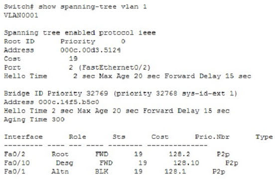
The show spanning-tree vlan command provides Spanning Tree Protocol (STP) information on the root switch, including the bridge ID, root path, and root cost, as well as information on the local switch.
This output indicates the following:
- The root switch has a bridge ID (Priority + MAC Address) of 0-000c.00d3.5124, while the local switch has a bridge ID of 32769-000c.14f5.b5c0. This indicates that the local switch is not the root switch for VLAN 1. Additional evidence that the local switch is not the root switch is the fact that the Fa0/1 port is blocking with a role listed as Altn. Only non- root bridges have blocking ports.
- For this switch, Fa0/1 represents the redundant link that needs to be blocked to prevent a switching loop.
- Interface Fa0/2 is the root port (the interface with the shortest path to the root switch).
- All three links have a cost of 19, which is the default cost of a single FastEthernet link.
- 802.1d is enabled in this switch, as indicated by the output Spanning tree enabled protocol ieee in line 2.
The show spanning-tree interface command will indicate the port role and state that a particular interface plays in each VLAN, but does not indicate the root bridge for a particular VLAN. Below is sample output from the show spanning-tree interface fastethernet0/1 command. In this example, RSTP is in use rather than 802.1d.

In this example, RSTP is in use rather than 802.1d.
In the above output, the Fa0/1 interface is not the root bridge for any of the three VLANs. It is the root port for VLANs 2 and 3. Root bridges have only designated ports. It is the alternate port for VLAN1, which means that Fa0/1 has a higher cost path to the root bridge than another interface in the topology, and will be in a blocking state as long as that other path is available.
The other options are incorrect because they are not valid Cisco IOS commands. The correct syntax would be show spanning-tree, not show spanning tree or show spantree.
Objective: LAN Switching Fundamentals
Sub-Objective: Configure, verify, and troubleshoot STP protocols
Exam Question 49
Which of the following loop avoidance mechanisms drives the requirement to create subinterfaces for each point-to-point connection in a partially meshed frame relay network?
A. split horizon
B. poison reverse
C. maximum hop count
D. feasible successor
Correct Answer:
A. split horizon
Answer Description:
Split horizon is the loop avoidance mechanism that drives the requirement to create sub interfaces for each point-to-point connection in a partially meshed frame relay network. Frame relay is a non-broadcast multiaccess (NBMA) network and obeys the rules of split horizon. This mechanism prohibits a routing protocol from sending updates out the same physical interface on which it was received. When the same physical interface is used to host multiple frame relay connections, this will prevent an update arriving from remote network A on the physical interface from being sent out the same interface to remote network B.
By creating a subinterface for each frame relay connection and assigning IP addresses to the subinterfaces rather than the physical interface, and by placing the subinterfaces into different subnets, split horizon will not see the “virtual” interfaces as the same interface and will allow these routing updates to be sent back out the same physical interface on which they arrived. It is important to map each subnet (or subinterface) to a remote Data Link Connection Identifier (DLCI) so that traffic to a remote network can be sent out the correct subinterface.
To summarize this discussion:
- Subinterfaces solve the NBMA split horizon issues.
- There should be one IP subnet mapped to each DLCI
Poison reverse is not the mechanism driving the requirement to create subinterfaces for each point-to-point connection in a partially meshed frame relay network. This mechanism requires a router to send an unreachable metric to the interface on which a network was discovered when it is learned from another interface that the network is no longer available.
Maximum hop count is not the mechanism driving the requirement to create sub interfaces for each point-to-point connection in a partially meshed frame relay network. Each routing protocol has a maximum hop count, which is the maximum number of hops allowed to a remote network before the network is considered “unreachable”.
Feasible successor is not the mechanism driving the requirement to create sub interfaces for each point-to-point connection in a partially meshed frame relay network. This is a concept unique to EIGRP that represents a secondary route to a network that is considered the “best” route of possible backup routes.
Objective: LAN Switching Fundamentals
Sub-Objective: Configure and verify Layer 2 protocols
Exam Question 50
How is load balancing achieved when implementing HSRP?
A. By configuring multiple gateways on the routers
B. By using multiple HSRP groups
C. By configuring the same priority on all HSRP group members
D. By configuring multiple virtual router addresses
Correct Answer:
B. By using multiple HSRP groups
Answer Description:
When implementing Hot Standby Router Protocol (HSRP), load balancing is achieved by using multiple HSRP groups. Routers configured for HSRP can belong to multiple groups and multiple VLANs. By configuring one group to be active for Router A and standby for Router B, and the second group to be active for Router B and standby for Router A, both routers A and B can be used to pass traffic, as opposed to one sitting idle.
Load balancing cannot be achieved by configuring multiple gateways on the routers. The routers have one IP address. Each group will have a virtual IP address. In the configuration below, line 4 configures the virtual IP address, and is therefore the address that clients will use as their gateway:
interface fastethernet 0/1

no switchport

ip address 192.168.5.5 255.2555.255.0

standby 1 ip 192.168.5.10
Load balancing cannot be achieved by configuring the same priority on all HSRP group members. If that were done, one of the routers would become active and the others would remain inactive standbys. The active router will be the one with the highest IP address.
Load balancing cannot be achieved by configuring multiple virtual router addresses. Each HSRP group can only have one virtual address.
Objective: Infrastructure Services
Sub-Objective: Configure, verify, and troubleshoot basic HSRP