The latest Cisco Certified Network Associate 200-301 CCNA certification actual real practice exam question and answer (Q&A) dumps are available free, which are helpful for you to pass the Cisco Certified Network Associate 200-301 CCNA exam and earn Cisco Certified Network Associate 200-301 CCNA certification.
Exam Question 11
What command would be used to verify trusted DHCP ports?
A. show mls qos
B. show ip dhcp snooping
C. show ip trust
D. show ip arp trust
Correct Answer:
B. show ip dhcp snooping
Answer Description:
The command show ip dhcp snooping is used to verify trusted DHCP ports. This command is used to verify which ports are intended to have DHCP servers connected to them.
DHCP snooping creates an IP address to MAC address database that is used by Dynamic ARP Inspection (DAI) to validate ARP packets. It compares the MAC address and IP address in ARP packets, and only permits the traffic if the addresses match. This eliminates attackers that are spoofing MAC addresses.
DHCP snooping is used to define ports as trusted for DHCP server connections. The purpose of DHCP snooping is to mitigate DHCP spoofing attacks. DHCP snooping can be used to determine what ports are able to send DHCP server packets, such as DHCPOFFER, DHCPACK, and DHCPNAK. DHCP snooping can also cache the MAC address to IP address mapping for clients receiving DHCP addresses from a valid DHCP server.
MLS QOS has no bearing on DHCP services, so show mls qos is not correct.
The other commands are incorrect because they have invalid syntax.
Objective: Infrastructure Security
Sub-Objective: Describe common access layer threat mitigation techniques
Exam Question 12
R1 and R2 are connected as shown in the diagram and are configured as shown in output in the partial output of the show run command.

R1 and R2 are connected as shown in the diagram

Configured as shown in output in the partial output of the show run command
The command ping R2 fails when executed from R1. What command(s) would allow R1 to ping R2 by name?
A. R1(config)#int S1
R1(config-if)#no ip address 192.168.5.5
R1(config-if)# ip address 192.168.5.9 255.255.255.252
B. R1(config)#no ip host R1
R1(config)# ip host R2 192.168.5.6 255.255.255.252
C. R1(config)#no hostname R2
R1(config)# hostname R1
D. R2(config)#int S1
R1(config-if)#no ip address 192.168.5.5
R1(config-if)# ip address 192.168.5.9 255.255.255.0
Correct Answer:
B. R1(config)#no ip host R1
R1(config)# ip host R2 192.168.5.6 255.255.255.252
Answer Description:
Both routers have been configured with the ip host command. This command creates a name to IP address mapping, thereby enabling the pinging of the device by address. On R1, the mapping is incorrect and needs to be corrected. Currently it is configured as ip host R1 192.168.5.6. It is currently mapping its own name to the IP address of R2.
To fix the problem, you should remove the incorrect IP address mapping and create the correct mapping for R2, as follows:
R1(config)#no ip host R1

R1(config)# ip host R2 192.168.5.6 255.255.255.252
Once this is done, the ping on R2 will succeed.
The IP address of the S1 interface on R1 does not need to be changed to 192.168.5.9 /30. In fact, if that is done the S1 interface on R1 and the S1 interface in R2 will no longer be in the same network. With a 30-bit mask configured, the network they are currently in extends from 192.168.5.4 – 192.168.5.7. They are currently set to the two usable addresses in that network, 192.168.5.5 and 192.168.5.6.
The hostnames of the two routers do need to be set correctly using the hostname command for the ping to function, but they are correct now and do not need to be changed.
The subnet mask of the S1 interface on R2 does not need to be changed to 255.255.255.0. The mask needs to match that of R1, which is 255.255.255.252.
Objective: Infrastructure Services
Sub-Objective: Troubleshoot client connectivity issues involving DNS
Exam Question 13
You network team is exploring the use of switch stacking.
Which of the following statements is NOT true of switch stacking?
A. The master switch is the only switch with full access to the interconnect bandwidth
B. Switches are connected with special cable
C. The stack has a single IP address
D. Up to nine switches can be added to the stack
Correct Answer:
A. The master switch is the only switch with full access to the interconnect bandwidth
Answer Description:
All switches in the stack have full access to the interconnect bandwidth, not just the master switch. The master switch is elected from one of the stack members. It automatically configures the stack with the currently running IOS image and a single configuration file.
The switches are connected with special cables that form a bidirectional closed loop path.
The stack has a single management IP address and is managed as a unit.
Up to nine switches can be in a stack.
Objective: LAN Switching Fundamentals
Sub-Objective: Describe the benefits of switch stacking and chassis aggregation
Exam Question 14
RouterA and RouterB, which connect two locations, are unable to communicate. You run the show running-configuration command on both router interfaces, RouterA and RouterB. The following is a partial output:

You run the show running-configuration command on both router interfaces, RouterA and RouterB.
Based on the information given in the output, what are two likely causes of the problem? (Choose two.)
A. The IP address defined is incorrect.
B. Both routers cannot have a clock rate defined.
C. Both routers cannot have an identical clock rate.
D. The Layer 2 framing is misconfigured.
E. At least one of the routers must have the ip mroute-cache command enabled.
Correct Answer:
A. The IP address defined is incorrect.
B. Both routers cannot have a clock rate defined.
Answer Description:
Two possible causes of the problem are that the IP addresses are incorrect as defined, or that both routers have a defined clock rate. The IP addresses on the routers are in different subnets. The IP addresses need to be changed to fall in the same subnet.
Both routers cannot have a clock rate configured. Only routers with a DCE cable connected should have a clock rate, which provides synchronization to the router connected to the DTE cable. In a point-to-point serial connection, the DCE cable connects to the DTE cable, providing a communication path between the two routers. If both computers have a clock rate configured, the routers will not communicate.
A matching clock rate is not the problem. The clock rates between two routers should match. The router connected to the DCE cable will provide the clock rate to the router connected to the DTE cable, resulting in matching clock rates.
The Layer 2 encapsulation refers to the Data Link protocol used on the link. In this case, the protocol is Point to Point Protocol (PPP), which is configured correctly on both ends as indicated by the matching encapsulation ppp statements in the output. The connection would be prevented from working if one of the routers were missing this setting (which would be indicated by the absence of the encapsulation ppp statement in its output), or if a different Layer 2 encapsulation type were configured, such as High-Level Data Link Control (HDLC).
The ip mroute-cache command is used to fast-switch multicast packets and would not cause the problem in this scenario.
Objective: Network Fundamentals
Sub-Objective: Configure, verify, and troubleshoot IPv4 addressing and subnetting
Exam Question 15
Which of the following commands will set the line speed of a serial connection that connects to a Channel Service Unit /Digital Service Unit (CSU/DSU) at 56 Kbps?
A. service-module 56000 clock rate speed
B. service-module 56k clock rate speed
C. bandwidth 56k
D. bandwidth 56000
Correct Answer:
B. service-module 56k clock rate speed
Answer Description:
The command service-module 56k clock rate speed will configure the network line speed for a 4-wire, 56/64-kbps CSU/DSU module.
The command service-module 56000 clock rate speed is incorrect because the speed must be stated in the form 56k (for Kbps), rather than 56000.
The bandwidth command is used to limit the amount of bandwidth used by an application when utilizing Quality of Service (QOS). It does not set the line speed of a serial connection that connects to a Channel Service Unit /Digital Service Unit CSU/DSU. Therefore, both the bandwidth 56k and the bandwidth 56000 commands are incorrect.
Objective: WAN Technologies
Sub-Objective: Describe WAN access connectivity options
Exam Question 16
You are discovering that there are differences between the configuration of EIGRP for IPv6 and EIGRP for IPv4. Which statement is true with regard to the difference?
A. A router ID is required for both versions
B. A router ID must be configured under the routing process for EIGRP for IPv4
C. AS numbers are not required in EIGRP for IPv6
D. AS numbers are not required in EIGRP for IPv4
Correct Answer:
A. A router ID is required for both versions
Answer Description:
Both versions of EIGRP require a router ID. The difference is that with EIGRP for IPv6, you must configure a router ID under the routing process if there are no IPv4 addresses on the router. In EIGRP for IPv4, the router can select one of the configured IPv4 addresses as the router ID.
A router ID can be configured under the routing process for EIGRP for IPv4, but it is not required. In EIGRP for IPv4, the router can select one of the configured Pv4 addresses as the router ID.
AS numbers are required in both versions of EIGRP.
Objective: Routing Fundamentals
Sub-Objective: Configure, verify, and troubleshoot EIGRP for IPv6 (excluding authentication, filtering, manual summarization, redistribution, stub)
Exam Question 17
Which of the following techniques is NOT used by distance vector protocols to stop routing loops in a network?
A. Split horizon
B. Spanning Tree Protocol (STP)
C. Holddowns
D. Route poisoning
Correct Answer:
B. Spanning Tree Protocol (STP)
Answer Description:
Spanning Tree Protocol (STP) is not used by distance vector protocols to stop routing loops in a network. STP is used to prevent switching loops in a switched network.
Routing loops can occur due to slow convergence and inconsistent routing tables, and can cause excessive use of bandwidth or complete network failure. An example of a routing table problem would be incorrectly configured static default routes. Suppose that Router A is connected to Router B, and the addresses of the interfaces on each end of the link connecting the two routers are as follows:
Router A 192.168.5.1/24
Router B 192.168.5.2/24
A partial output of the routing tables of the two routers is shown below. Router B hosts the connection to the Internet.
routerA# show ip route

Gateway of last resort is 192.168.5.2 to network 0.0.0.0

<Output omitted>

routerB# show ip route

Gateway of last resort is 192.168.5.1 to network 0.0.0.0

<Output omitted>
From the limited information shown above, you can see that Router A is pointing to Router B for the default route, and Router B is pointing to Router A for the default route. This will cause a routing loop for any traffic that is not in their routing tables. For example, if a ping were initiated to the address 103.5.6.8 and that address was not in the routing tables of Routers A and B, the most likely message received back would NOT be “destination unreachable” but “TTL expired in transit.” This would be caused by the packet looping between the two routers until the TTL expired.
The following techniques are used by distance vector protocols to stop routing loops in a network:
- Split horizon stops routing loops by preventing route update information from being sent back over the same interface on which it arrived.
- Holddown timers prevent regular update messages from reinstating a route that is unstable. The holddown timer places the route in a suspended, or “possibly down” state in the routing table and regular update messages regarding this route will be ignored until the timer expires.
- Route poisoning “poisons” a failed route by increasing its cost to infinity (16 hops, if using RIP). Route poisoning is combined with triggered updates to ensure fast convergence in the event of a network change.
Objective: Routing Fundamentals
Sub-Objective: Compare and contrast distance vector and link-state routing protocols
Exam Question 18
What command should you use to quickly view the HSRP state of the switch for all HSRP groups of which the switch is a member?
A. switch# show standby brief
B. switch# show ip interface brief
C. switch# show hsrp
D. switch# show standby
Correct Answer:
A. switch# show standby brief
Answer Description:
The command show standby brief should be used to quickly view the HSRP state of a switch for all HSRP groups of which it is a member. The summary information it provides includes the group number, priority, state, active device address, standby address, and group address.
The command show standby can be used to display detailed information about HSRP groups of which a switch is a member. This command would not provide a quick view. This command displays information about HSRP on all configured interfaces and for all HSRP groups. It also displays hello timer information and the expiration timer for the standby switch.
The command show ip interface brief is useful in that lists the interfaces and displays the basic IP configuration of each. This output would include the IP address of the interface and the state of the interface, but not HSRP information.
The command show hsrp is not a valid command due to incorrect syntax.
Objective: Infrastructure Services
Sub-Objective: Configure, verify, and troubleshoot basic HSRP
Exam Question 19
When packets are transmitted from one host to another across a routed segment, which two addresses are changed? (Choose two.)
A. source IP address
B. source MAC address
C. destination IP address
D. destination MAC address
Correct Answer:
B. source MAC address
D. destination MAC address
Answer Description:
When packets move from one LAN segment to another LAN segment across a router, the source and destination Media Access Control (MAC) addresses in the packet change.
Packets destined for a remote network must be forwarded by a router that is typically the sending host’s default gateway. The IP address of the remote host is inserted into the packet, while the MAC address of the default gateway is inserted as the Layer 2 address. This ensures that the packet is received by the default gateway. The router then examines the destination IP address, performs a route lookup, and forwards the packet toward the destination, inserting its MAC address as the source MAC address. If the next hop is another router, then the destination MAC address is replaced with the next router’s MAC address. This process is repeated by each router along the path (inserting its own MAC address as the source MAC address and inserting the MAC address of the next router interface as the destination MAC address) until the packet is received by the remote host’s default gateway. The destination gateway then replaces the destination MAC address with the host’s MAC address and forwards the packet.
In the diagram below, when the host located at the IP address 10.0.1.3 sends data to the host located at IP address 10.1.1.3, the Layer 2 and Layer 3 destination addresses will be bb.bb.bb.bb.bb.bb and 10.1.1.3, respectively. Note that the Layer 2 destination address matches the host’s default gateway and not the address of the switch or the destination host.
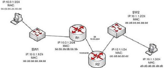
Note that the Layer 2 destination address matches the host’s default gateway and not the address of the switch or the destination host.
It is incorrect to state that the source IP address or the destination IP address change when packets transfer from one host to another across a routed segment. The Internet Protocol (IP) addresses within the packets do not change because this information is needed to route the packet, including any data returned to the sender.
Data return to the sending host is critically dependent on the destination having a default gateway configured and its router having a route back to the sender. If either is missing or configured incorrectly, a return is not possible. For example, when managing a switch remotely with Telnet, the switch cannot be located on the other side of a router from the host being used to connect if the switch does not have a gateway configured. In this case, there will no possibility of a connection being made because the switch will not have a return path to the router.
Objective: Routing Fundamentals
Sub-Objective: Describe the routing concepts
Exam Question 20
You are connecting a new computer to Switch55. The new computer should be placed in the Accounting VLAN. You execute the show vlan command and get the following output:

You execute the show vlan command and get the following output.
Examine the additional network diagram.

Examine the additional network diagram.
What action should you take to place the new computer in the Accounting VLAN and allow for inter-VLAN routing?
A. Connect the new computer to Fa0/1
B. Connect the new computer to Fa0/14
C. Connect the new computer to Fa0/5
D. Configure a dynamic routing protocol on the router interface
Correct Answer:
C. Connect the new computer to Fa0/5
Answer Description:
Switchport Fa0/5 can be used to place the computer in the Accounting VLAN.
The diagram indicates that a router has been configured as a “router-on-a-stick” to perform inter-VLAN routing between VLANs 10, 20, 30 and 40. The show vlan output indicates that interfaces Fa0/5, Fa0/15, and Fa0/6 have been assigned to VLAN 20, the Accounting VLAN:
20 accounting active Fa0/5, Fa0/6, Fa0/15
Switchports Fa0/1 and Fa0/14 are both in the default VLAN, as indicated by the portion of the output describing the switch ports that are unassigned and therefore still residing in the default VLAN:
1 default active Fa0/1, Fa0/2, Fa0/3,

Fa0/7, Fa0/8, Fa0/9,

Fa0/14, Fa0/16, Fa0/23,

Fa0/19, Fa0/20, Fa0/23
It is not necessary to configure a dynamic routing protocol on the router. Since the router is directly connected to all four subinterfaces and their associated networks, the networks will automatically be in the router’s routing table, making inter-VLAN routing possible.
Objective: LAN Switching Fundamentals
Sub-Objective: Configure, verify, and troubleshoot VLANs (normal/extended range) spanning multiple switches