5G networks promise faster and more reliable communication that will open doors to exciting application areas, but working with 5G introduces new challenges in design and test.

Getting Started in 5G – Overcome New Radio Device Design Challenges
Keysight’s 4-part article series, First Steps in 5G, will get you started on the road to mastering the complexities of 5G.
- Part 1: 5G New Radio Standard helps you understand the 5G NR specifications
- Part 2: Millimeter-Wave Spectrum covers 5G NR frequency ranges, spectrum trials by region, and insights on test plans
- Part 3: MIMO and Beamforming outlines how to evaluate antenna beam patterns for quality of service
- Part 4: Over-the-Air Test will get you up to speed on OTA test methodologies — one of the most challenging aspects of 5G
Content Summary
Part 1: 5G New Radio Standard
Embracing 5G
New Challenges Ahead
5G NR Specifications
Terminology
Flexible waveform and numerology
Low latency mini-slots
Flexible slot structures
Flexible bandwidth parts
Greater throughput through massive MIMO and beam steering
CSI to improve beamforming reliability
A 5G NR waveform
Design and Test Must Evolve
Part 2: Millimeter-Wave Spectrum
A Look at 5G Spectrum
mmWave Signal Quality Challenges
Characterizing signal quality
Defining a measurement solution
A 5G NR mmWave measurement
Addressing the Challenges of mmWave
Part 3: MIMO and Beamforming
MIMO Technology Basics
MIMO and Beamforming Challenges and Solutions
Beam pattern verification
mmWave link integrity
Device performance optimization under real-world conditions
Choosing the Right Tools for Evaluating Antenna Beam Patterns
Part 4: Over-the-Air Test
New Test Methodologies Required for mmWave
OTA Test Challenges and Solutions
Challenge 1: Excessive path loss and distance at mmWave frequencies
Challenge 2: mmWave OTA test methods not fully defined
Direct far-field method
Indirect far-field method
Near-field to the far-field transform method
Challenge 3: Measuring device performance in real-world conditions
Implementing Evolving OTA Testing Methods
Part 1: 5G New Radio Standard
5G offers a dramatic improvement over 4G’s capabilities. The physical layer specifications began with the 5G New Radio (NR) initial release 15. Release 15 specifications focus on enhanced mobile broadband (eMBB) and ultra-reliable, low-latency communications (URLLC) to achieve very fast data rates and provide very low latency in wireless communications.
These specifications introduce new challenges for device and component designers. Measurements become more critical, as does the need to validate protocols for the many different test cases and verify radio-frequency performance to deliver the expected quality of service. Massive multiple-input / multiple-output (MIMO) and beam steering introduce challenges in beam management. The use of millimeter-wave (mmWave) frequencies poses challenges in signal quality, and the requirement of over-the-air (OTA) testing makes validation even more difficult. This four-part white paper series explores the lower layers of the communication stack and considerations for addressing new challenges in designing and testing 5G devices.
Embracing 5G
Emerging technologies such as cloud computing, artificial intelligence (AI) and machine learning, augmented and virtual reality, the Internet of Things, and billions of connected devices push the boundaries of wireless communications systems. 5G technology promises faster, more reliable, and near-instant connections. Imagine live events and video games experienced in real-time. Phone and video calls feel close and intimate. Smart devices paired with AI create a customized and personalized environment for everyone.
5G NR will work alongside 4G and even utilize the 4G core network for data and control planes in non-standalone mode. 5G, 4G, and Wi-Fi need to coexist on the same carriers and utilize unlicensed bands to increase capacity below 6 GHz. 5G NR releases 15 sets the foundation to enable flexibility that will accommodate future releases of 5G communications. The physical layer is the first step in the adoption of 5G NR. It defines the structure that makes up the radio signal and the signal communication through the air interface.
New Challenges Ahead
The challenges associated with implementing device designs in the physical layer include the following:
- Flexible time and frequency intervals enable low latency but result in complex channel coding, signal-quality challenges, and numerous test cases.
- Bandwidth parts yield more efficient use of spectrum, but this introduces coexistence issues.
- Massive MIMO and mmWave beam steering enable higher throughput and capacity gains, but also introduce new challenges in beam management.
- The use of mmWave frequencies allows for greater channel bandwidths but introduces challenges in signal quality and the need for OTA tests.
Part 1 of this series introduces the 5G NR specifications and describes the key features that will enable advances in 5G. Future installments dive deeper into the challenges of implementing 5G NR specifications.
5G NR Specifications
NR release 15 specifies a new air interface to enable higher data throughput and low-latency use cases. The key to enabling higher data throughput is the addition of the mmWave spectrum up to 52.6 GHz. At these higher frequencies, the more contiguous spectrum is available to send more data through the channel. Release 15 specifies a maximum carrier bandwidth up to 400 MHz and up to 16 component carriers that, when aggregated, add up to 800 MHz of bandwidth. Also, flexibility and scalability in the slot structure help support the many new and diverse use cases expected in 5G. Figure 1 maps out the contributions of different specifications to deliver a flexible and scalable physical layer and shows the advantages of 5G NR.
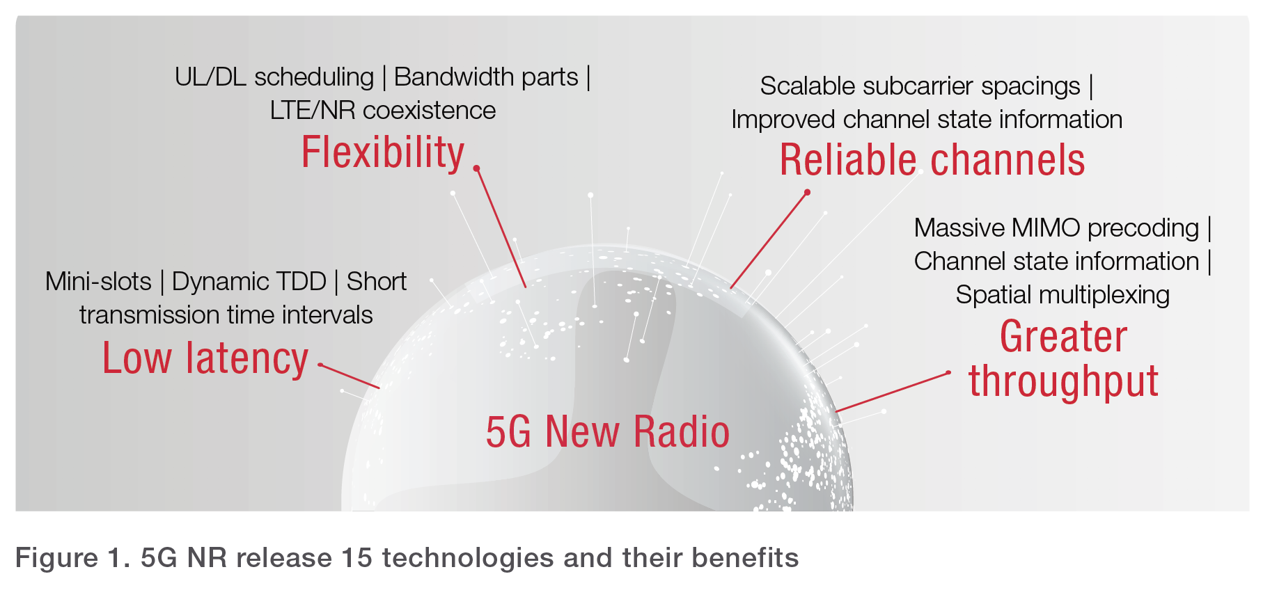
Figure 1. 5G NR release 15 technologies and their benefits
Terminology
- CP — cyclic prefix
- CP-OFDM — cyclic prefix orthogonal frequency division multiplexing
- CSI — channel state information
- DFT-s-OFDM — discrete Fourier transform spread OFDM
- DL — downlink
- eMBB — enhanced mobile broadband
- FDD — frequency division duplex
- LTE-LAA — Long-Term Evolution Licensed Assisted Access
- MIMO — multiple-input / multiple-output
- mMTC — massive machine-type communications
- mmWave — millimeter wave
- NR — New Radio
- OTA — over the air
- PAPR — peak-to-average power ratio
- SFI — slot format indicator
- TDD — time division duplex
- TTI — the transmission time interval
- UL — uplink
- URLLC — ultrareliable, low- latency communications
Flexible waveform and numerology
In 5G NR, cyclic prefix orthogonal frequency division multiplex (CP-OFDM) is the modulation format (or waveform) in the downlink (DL) and uplink (UL). CP-OFDM use is well-known for DL transmissions but is new for UL transmissions in mobile. Having the same waveform in both UL and DL enables easier device-to-device communication in future releases. Discrete Fourier transform spread OFDM (DFT-s-OFDM) is an optional waveform in the UL. DFT-s- OFDM uses a single transmission, which is helpful in limited-power scenarios.
Unlike 4G, NR allows for scalable OFDM numerology (μ) where the subcarrier spacings are no longer fixed to 15 kHz. With NR, subcarrier spacing scales by 2μ x 15 kHz to cover different services. Lower-frequency bands use 15, 30, and 60 kHz subcarrier spacings and higher frequency bands use 60, 120, and 240 kHz subcarrier spacings. Scalable numerology enables scalable slot duration to optimize for different service levels in throughput, latency, or reliability. Larger subcarrier spacing at higher frequencies also helps with the robustness of the waveform since integrated phase noise is an issue in mmWave designs. Figure 2 shows how the different subcarrier spacings and the transmission time interval (TTI) associated with each scales the size of the slot.

Figure 2. Relationship between subcarrier spacings and time durations
In an OFDM system, using cyclic prefix (CP) mitigates the effects of channel delay spread and inter-symbol interference (ISI). CP provides a buffer to protect the OFDM signal from ISI by repeating the end of the symbol at the start of the same symbol. While this reduces the achievable data rate, it eliminates the ISI up to the length of the CP. In 5G NR, as subcarrier space changes, the CP length scales accordingly, making it possible to adapt the CP length to the channel conditions.
Low latency mini-slots
URLLC is one of three primary 5G use cases and is achieved partially through mini-slots. In Long Term Evolution (LTE), transmissions adhere to the standard slot boundaries, but they are not optimized for minimal latency. A standard slot has 14 OFDM symbols, shown in dark blue in Figure 3. As the subcarrier spacing increases, the slot duration decreases, as shown in light blue. A mini-slot is shorter in duration than a standard slot and located anywhere within the slot. A mini-slot is 2, 4, or 7 OFDM symbols long. Mini-slots provide low-latency payloads with an immediate start time without the need to wait for the start of a slot boundary.

Figure 3. Slots and mini-slots within a subframe and their associated slot duration time
Flexible slot structures
NR subframe structure also allows for dynamic assignments of the OFDM symbol link direction and control within the same subframe. By using this dynamic time division duplex (TDD) mechanism, the network dynamically balances UL and DL traffic requirements and includes control and acknowledgment all in the same subframe. The slot format indicator denotes whether a given OFDM symbol in a slot is used for uplink or downlink, or if it is flexible.

Figure 4. Slot structure can be mixed to improve traffic dynamically
Flexible bandwidth parts
In LTE, carriers are narrower in bandwidth — up to 20 MHz maximum. When aggregated, they create a wider channel bandwidth of up to 100 MHz. In 5G NR, the maximum carrier bandwidth is up to 100 MHz in frequency range 1 (FR1) — up to 24 GHz — and up to 400 MHz in the frequency range 2 (FR2) — up to 52.6 GHz. New in 5G NR is bandwidth parts where the carrier is subdivided for different purposes. Each bandwidth part has its numerology and is signaled independently. One carrier can have mixed numerologies to support a mixed level of services, such as power saving or multiplexing of numerologies and services in unlicensed bands. However, only one bandwidth part in the UL and one in the DL are active at a given time. Bandwidth parts will support legacy 4G devices with new 5G devices on the same carrier. With 4G, 5G, and potentially Wi-Fi multiplexing services, it is necessary to minimize both in-band and out-of-band emissions. Figure 5 shows examples of how bandwidth parts support different services in a given carrier.

Figure 5. Bandwidth parts support multiplexing of different services on the same carrier
Greater throughput through massive MIMO and beam steering
Just like any previous generation upgrades, throughput is key to making 5G communications successful. 5G boosts throughput in multiple ways:
- Wider overall channel bandwidths enable sending more data through the air interface.
- Spatial multiplexing sends independent streams of data through multiple antennas at a given time and frequency and uses enhanced channel feedback to improve throughput.
Enhanced channel feedback improves throughput since the signal is optimized for transmission with advanced channel coding.
Massive MIMO and beam steering technologies improve throughput. NR release 15 specifies frequency use up to 52.6 GHz with up to 400 MHz bandwidth per carrier and aggregation of multiple carriers for up to 800 MHz channel bandwidth. Operating at mmWave frequencies, however, introduces challenges in path loss, blockage, and signal propagation. Beam steering is a key technology to overcome these issues. NR specifies new initial access procedures to ensure alignment of the directional transmissions used in beam steering. Figure 6 shows new initial access techniques where the base station uses beam sweeping to transmit multiple beams, identify the strongest beam, and establish a communication link. Validating initial access, beam management, and throughput achieved through the wireless link are key factors for successful beam steering implementation in 5G.

Figure 6. Beam sweeping and initial access
CSI to improve beamforming reliability
Channel state information (CSI) will help with 5G NR beamforming reliability. 5G NR specifies a new beam management framework for CSI acquisition. The framework reduces coupling between CSI measurements and reporting to control different beams dynamically. CSI uses channel estimation to intelligently change the precoding and adapt the beam to a specific user. The better and more precise this CSI information, the better the link adaptation.
A 5G NR waveform
It is important to understand the frequency-, time-, and modulation-domain analysis of 5G NR waveforms. It is essential to have software and hardware that can create and analyze a 5G waveform for different use cases at sub-6 GHz and in the new mmWave frequencies with greater bandwidths. New capabilities in NR specifications — including flexible numerologies with different subcarrier spacing, dynamic TDD, and bandwidth parts — add to the complexity of creating and analyzing the waveform. Figure 7 shows two NR waveforms created with Keysight’s 5G Signal Studio software and signal generators and the associated analysis done by Keysight’s 89600 VSA NR software.

Figure 7. Using 5G signal generators, signal analyzers, and VSA software to analyze 4G and 5G waveforms
Design and Test Must Evolve
5G offers many advances in throughput, low latency, and massive machine-to-machine communications. The initial 5G NR release 15 provides flexibility and forward compatibility, but these benefits present significant implementation challenges. Along every measurement step — through simulation, design, and validation — are considerations and challenges in meeting these standards. Design and test for 5G devices must evolve to accommodate the validation of the many required test cases. 5G devices need to ensure robust, high-throughput connections at mmWave frequencies and design for the coexistence of 5G NR with 4G and Wi-Fi. In part 2 of this four-part 5G NR white paper series, we review the challenges with implementation in the mmWave frequencies and considerations for your 5G NR device design.
Part 2: Millimeter-Wave Spectrum
The goals for 5G are aggressive. The enhanced mobile broadband (eMBB) use case targets peak data rates as high as 20 Gbps in the downlink (DL) and 10 Gbps in the uplink (UL) to support new applications such as high-speed streaming of 4K or 8K UHD movies. While there are different ways to improve data rates, the spectrum is at the core of enabling higher mobile broadband data rates. 5G New Radio (NR) specifies new frequency bands below 6 GHz and extends into millimeter-wave (mmWave) frequencies where more contiguous bandwidth is available for sending lots of data.
While consumers will appreciate the increased bandwidth, it introduces challenges on link quality requirements at mmWave frequencies. Impairments are not an issue at sub-6 GHz but become more problematic at mmWave frequencies. Extra consideration is needed to determine test approaches that provide the precision required to accurately evaluate 5G components and devices.
A Look at 5G Spectrum
Spectrum harmonization across regions is limited. It is challenging for designers to deliver a full range of capabilities and coverage for consumers around the world. 5G NR specifies frequency up to 52.6 GHz, and even the initial operating bands open up almost 10 GHz of a new spectrum.
- Frequency range 1 (FR1): 410 MHz to 7.125 GHz adds 1.5 GHz of new spectrum in frequency bands 3.3 — 4.2 GHz, 3.3 — 3.8 GHz, 4.4 — 5 GHz, and 5.925 — 7.125 GHz.
- Frequency range 2 (FR2): 24.25 — 52.6 GHz initially added 8.25 GHz of new spectrum in frequency bands 26.5 — 29.5 GHz, 24.25 — 27.5 GHz, and 37 — 40 GHz.
Studies and trials in key regions and operating bands in new FR1 territory (> 2.5 GHz) and FR2 have surfaced in initial launches, as shown in Table 1.

Table 1. 5G spectrum trials from sub-6 GHz to mmWave frequencies
- Below 1 GHz, there are multiple bands of interest in 600, 700, and 800 MHz to support the Internet of Things and other mobile services.
- 1 — 6 GHz aims to increase coverage and capacity. A primary target in China, Europe, South Korea, and Japan is the 3.3 — 3.8 GHz range. China and Japan are also considering the 4.4 — 4.9 GHz range.
- Above 6 GHz will primarily support the need for ultra-high broadband use cases. Initial mmWave targets are 28 GHz and 39 GHz in Japan and the US. While 5G NR release 15 specifies frequency range up to 52.6 GHz, studies are underway for future releases to include 52.6 up to 110 GHz.
Similar to Long Term Evolution (LTE), multiple component carrier aggregations provides larger bandwidths, up to a maximum bandwidth of 800 MHz at FR2. For the initial 5G NR release, individual countries will decide on the amount of spectrum deployed. Frequency, bandwidth, and waveforms will continue to evolve with future 5G NR releases to support new use cases.
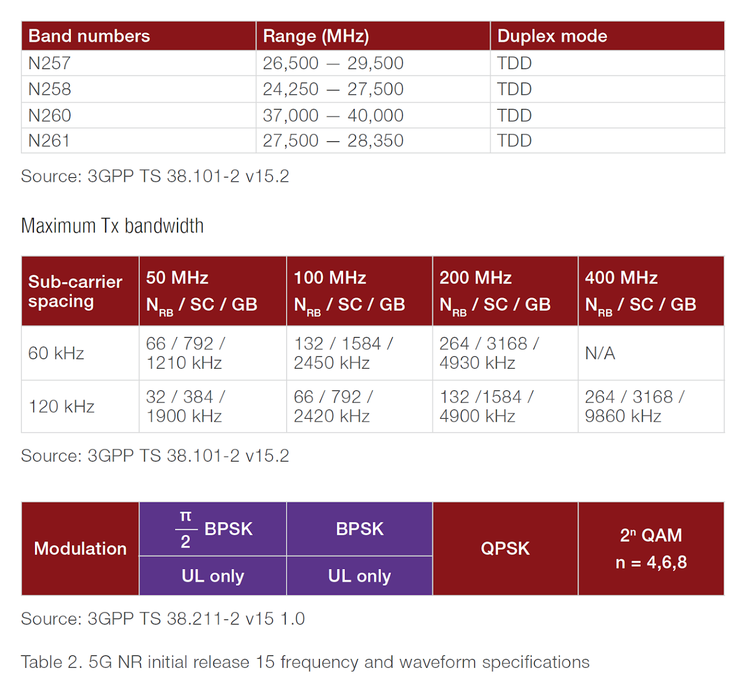
Table 2. 5G NR initial release 15 frequency and waveform specifications
FR1 introduces challenges for designs in the new bands above 3 GHz because of the complexity of the test cases, coexistence issues, and validating massive multiple-input / multiple-output (MIMO) designs over the air. FR1 is an evolution of existing LTE-Advanced capabilities, and the implementation of mmWave designs will introduce more significant challenges.
Fixed wireless access was the first mmWave introduction at the end of 2018. Initial 5G fixed wireless access implementations operate in nonstandalone mode, utilizing the 4G evolved packet core and eNodeB as an anchor and control plane. A significant change will happen when mmWave implementations go mobile. There will be new challenges establishing and maintaining the communication link when the device is moving across a parking lot, down a highway, or even on a high-speed train. Trials have been underway for some time to ensure the viability of different mmWave mobile use cases. Refining the channel models for the different use cases will require that components and devices have the necessary performance to operate in mmWave frequency bands.
mmWave Signal Quality Challenges
Many factors impact signal quality, including baseband signal processing, modulation, filtering, and upconversion. With wider channel bandwidths expected at mmWave frequencies, common signal impairments impact baseband and RF designs. These impairments become more problematic at higher frequencies or with wider bandwidths. Inherent in orthogonal frequency-division multiplexing (OFDM) systems, orthogonal properties prevent interferences between overlapping carriers. However, issues such as IQ impairments, phase noise, linear (AM to AM) and nonlinear (AM to PM) compression, and frequency error cause distortion in the modulated signal. Phase noise is one of the most challenging factors in mmWave OFDM systems. Too much phase noise in designs results in each subcarrier interfering with other subcarriers, leading to impaired demodulation performance.
Such issues impact the performance of your designs and are difficult to resolve. Device designs need to overcome the physical challenges in wide bandwidth and mmWave signals. Test solutions require better performance than the device under test (DUT) to properly measure and characterize signal quality without introducing new issues.
Characterizing signal quality
Evaluating a signal’s modulation properties provides one of the most useful indicators of signal quality. Viewing the IQ constellation helps in determining and troubleshooting distortion errors. Another key indicator of a signal’s modulation quality is a numeric error vector magnitude (EVM) measurement that provides an overall indication of waveform distortion.
5G NR specifies a cyclic prefix OFDM (CP-OFDM), which is a multicarrier modulation scheme. An EVM measurement reflects any variation in a circuit’s phase, amplitude, or noise seen in wideband signals. EVM is the normalized ratio of the difference between two vectors: IQ measured signal and IQ reference (IQ reference is a calculated value), as shown in Figure 1. EVM is a measure of the average amplitude of the error vector from the ideal reference point. EVM is typically measured in decibels (dB) or as a percentage.

Figure 1. Understanding the EVM calculation
With the expected use of higher-order modulation schemes in 5G (up to 256 QAM initially, and up to 1024 QAM in the future), components and devices require a better EVM result as modulation density increases. For example, Table 3 shows how 3GPP EVM requirements for user equipment (UE) get tighter as modulation density increases.

Table 3. 3GPP TS 38.101-1 EVM requirements for different 5G modulation schemes
Spectrum measurements are also necessary to validate a signal’s RF performance. 5G UE spectrum measurements for transmitting products include transmitted power, occupied bandwidth (OBW), adjacent channel power ratio (ACPR), spectrum emissions mask (SEM), and spurious emissions.
A test solution needs enough performance to evaluate the constellation diagram and measure the EVM required by 5G components and devices. Flexibility to make spectrum measurements and scale to higher frequencies and bandwidths is necessary as 5G standards evolve.
Defining a measurement solution
Achieving high-quality measurements of high-bandwidth devices at mmWave frequencies requires a test solution with EVM performance that is better than the product or system under test. Typical guidelines to follow include these:
- for the component test, 10 dB better than the system as a whole
- for system test, 3 dB better than the source from the radio standard
When measuring a transmitter, receiver, transceiver, or another component in a wireless device, a test solution typically consists of a stimulus and DUT; DUT and analyzer; or stimulus, DUT, and analyzer depending on the DUT. You can typically conduct measurements in baseband and sub-6 GHz using cables. Centimeter-wave or mmWave frequencies, however, will likely require an over-the-air measurement. That is because of the high level of integration expected in the antennas and RF integrated circuits, resulting in no connector test points for the conducted test.
Figure 2 shows Keysight’s 5G R&D Test Bed setup. It has the performance needed to evaluate 5G components and devices for impairments at mmWave frequencies. A vector signal generator provides a digitally modulated 5G NR signal to the DUT. A vector signal analyzer captures the RF signal properties out of the DUT and digitizes the modulated signal for analysis. This test solution offers flexible configurations to address the many combinations of frequency, bandwidth, and fidelity required for testing 5G components and devices.

Figure 2. 5G R&D Test Bed with 5G NR-ready hardware and software, including signal optimizer calibration software
The test setup itself can introduce other sources of error in a measurement system. When considering a test setup at higher frequencies with wider bandwidths, remember that test fixtures, cables, adaptors, couplers, filters, preamplifiers, splitters, and switching between the DUT and measurement equipment have a greater impact than in sub-6 GHz measurement systems. Calibrating the measurement system to the reference plane at the location of the DUT is essential to achieve the highest measurement accuracy. The goal is to see the true characteristics of the DUT without seeing the impacts of the test setup. The measurement system needs to perform better than the DUT design goals. Measurements at the DUT plane are more accurate and repeatable. A proper system-level calibration eliminates uncertainties caused by test fixtures in frequency and phase and is valuable for very wide bandwidth signals. The 5G R&D Test Bed solution includes the signal optimizer software that moves the calibration plane from the test equipment to the DUT reference plane, as shown in Figure 2.
Connectors, cables, and adapters
In addition to calibration, proper use of cables, connectors, and adapters improves the accuracy of your test setup. The materials, structures, and geometries of these components are designed for a specific operating frequency range. Avoid compromising the performance of an expensive test system with poor-quality or inappropriate cabling and accessories. Since most mmWave spectrum analyzers are used in an environment that also includes work at lower frequencies, it can be tempting to use connectors designed for these lower frequencies. However, smaller wavelengths demand smaller dimensions in the cables and connectors. For mmWave measurements, do not use common subminiature version A (SMA) and precision 3.5 mm accessories.
For mixed-frequency environments, consider standardizing on 2.4 mm or 2.92 mm accessories. Although they have slightly more insertion loss than SMA and 3.5 mm (primarily above 30 GHz), 2.4 mm and 2.92 mm accessories can cover all lower frequencies and offer superior repeatability.
A 5G NR mmWave measurement
Proper selection of test equipment, connectors, adapters, and system-level calibration enables high-performance measurements to evaluate the true performance of 5G components or devices. Figure 3 shows a calibrated measurement of a 5G antenna using Keysight’s 5G R&D Test Bed solution. It enables the characterization of 5G NR devices from RF to mmWave frequencies with precision and modulation bandwidths up to 2 GHz. 5G NR-compliant software lets you easily create and analyze waveforms with 5G numerology, uplink, and downlink to test 5G NR and LTE integration and coexistence.

Figure 3. Analysis of a 5G NR 256 QAM signal with the antenna pattern
Addressing the Challenges of mmWave
5G operation in mmWave frequency bands is now a reality. 5G NR release 15 specifies mmWave operation up to 52.6 GHz with up to 800 MHz aggregated channel bandwidth. At mmWave frequencies, signals are more susceptible to impairments, requiring extra consideration in the selection of test solutions, cables, and connectors. System-level calibration is also essential to achieve accurate measurements. Keysight’s 5G R&D Test Bed enables precision characterization of 5G NR device signal quality from RF to mmWave frequencies. It provides the performance and bandwidth needed, as well as the flexibility to scale as the 5G standard evolves.
Part 3: MIMO and Beamforming
Multiple-input / multiple-output (MIMO), beam steering, and beamforming are the most talked-about technologies in 5G. They are essential for delivering the 100x data rates and the 1,000x capacity goals the International Mobile Telecommunications-2020 (IMT-2020) vision specifies.
According to the Ericsson Mobility Report (June 2019), mobile data traffic grew 82% year on year in the first quarter of 2019. The report predicts mobile traffic will rise at a compound annual growth rate of 30% between 2018 and 2024. It forecasts a total of 8.8 billion mobile subscriptions by 2024, including 1.9 billion for 5G enhanced mobile broadband.
MIMO is one important approach to improve the capacity and efficiency of a network to meet these demands. These multi-antenna technologies must support multiple frequency bands — from sub-6 GHz to millimeter-wave (mmWave) frequencies — across many scenarios, including massive Internet of Things connections and extreme data throughput. Implementing MIMO on 5G devices brings several design challenges, including 3D antenna beam pattern verification, mmWave link integrity, and optimization of device performance under real-world conditions.
MIMO introduces three key design challenges:
- 3D antenna beam pattern verification
- Validation of mmWave link integrity
- Device performance optimization under real-world conditions
MIMO Technology Basics
Understanding the challenges requires a basic knowledge of the techniques used to deliver high-quality, robust signals to and from the 5G device. There are different techniques for implementing MIMO, each offering distinct benefits and compromises.

Figure 1. Spatial multiplexing MIMO configurations
Spatial diversity helps improve reliability in many forms of radio-frequency (RF) communication. Spatial diversity consists of sending multiple copies of the same signal via multiple antennas. This common technique increases the chances of properly receiving the signal, improving reliability.
Spatial multiplexing is a different multiple-antenna technique that feeds independent data into each antenna, with all antennas transmitting at the same frequency. Spatial multiplexing creates multiple channels with independent streams, which increases the overall data capacity.
Beam steering and beamforming use multiple antennas to create directional transmissions, increasing gain in exchange for a beam that must accurately point at the receiving antenna. Beamforming is more complex than beam steering, incorporating channel feedback to manipulate the beam shape and direction in real-time. Spatial multiplexing with beamforming increases signal robustness with the added advantage of improved throughput. Multi-user MIMO is a technique that uses multiple beams directed at different devices to achieve greater spectral efficiency.
MIMO and Beamforming Challenges and Solutions
MIMO and beamforming at mmWave frequencies introduce many challenges for device designers. 5G New Radio (NR) standards provide the physical-layer frame structure, new reference signal, and new transmission modes to support 5G enhanced mobile broadband (eMBB) data rates. Designers must understand the 3D beam patterns and ensure that the beams can connect to the base station and deliver the desired performance, reliability, and user experience. The following techniques are essential to successfully implementing your 5G device design:
- 3D antenna beam pattern verification
- mmWave link integrity validation
- Device performance optimization under real-world conditions
Beam pattern verification
Beam performance validation requires measurements of 3D antenna beam patterns to verify the right antenna gain, side lobes, and null depth for the full range of 5G frequencies and bandwidths. The location of the side lobes and nulls is important to tune the antenna and maximize the radiated efficiency of the signal.
While design verification of prototypes is crucial, building mmWave prototypes are costly. Modeling an antenna in a simulated system with channel models and base station links provides insights early in the design cycle that reduce prototype and rework costs early. The simulation data becomes an important part of the design process and helps with troubleshooting throughout the development workflow.
Figure 2 shows a link-level simulation with mmWave channel models to help you understand the performance of a simulated antenna. With this approach, it is possible to add different impairments to the simulation to optimize your design before developing hardware prototypes.

Figure 2. Electronic system-level tools such as Keysight’s SystemVue help designers quickly integrate and validate their designs before moving to hardware
As mentioned above, once a design moves into hardware, designers must validate that the device produces the correct beam width, null depth, and gain over the required range. It must also meet power output limits. In hardware, this requires over-the-air (OTA) test methods.

Figure 3. Indirect far-field compact test antenna range for mmWave OTA testing
Multi-element antenna arrays will be used on mobile devices to implement beam steering or beamforming. Phased array antennas are a practical and low-cost means of dynamically creating and pointing beams in the desired direction, also known as beam steering. An array of smaller antenna elements forms a phased array antenna. By varying the relative phases and amplitudes of the signals applied to the individual elements, the antenna array can steer and shape a beam in a chosen direction. These arrays will be incorporated into RF integrated circuits and will require OTA testing as there are no probe points to make conducted measurements.
mmWave link integrity
LTE systems use antennas covering large angular areas to cast a wide net for potential users. 5G will use narrow beams to overcome mmWave signal propagation issues, but this makes it more difficult for the user equipment (UE) to find the beams from the base station. Maintaining a quality link is also an issue, especially when the device moves through the network. 5G NR release 15 specifies new procedures for initial access and attach when establishing the wireless link connection. Since neither the device nor the base station knows the other’s location, the base station uses beam sweeping to transmit channel information in sync blocks across the spectrum, as shown in Figure 4. The UE determines the strongest match and transmits back to the base station. Once the base station knows the direction of the UE, it establishes a communication link.
Beam acquisition and tracking, beam refinement, beam feedback, and beam switching procedures exist. It takes longer to establish this connection when using mixed numerologies. Designers need to implement, validate, and optimize all these functions, or the user will experience dropped calls or poor performance.
Testing the protocol early in the development cycle ensures that the device can establish and maintain a call. A network emulator with a built-in protocol state machine emulates network signals and tests the resulting device signals to verify and optimize initial access and beam management.

Figure 4. 5G initial access and beam management
Device performance optimization under real-world conditions
Key performance indicators for the wireless communications system include throughput and latency. If the latency — or delay — is too great, then the end-user experience suffers. The different layers of the protocol stack need to work together to deliver the latency and throughput targets of the 5G system. It is important to understand how the device will perform, not only when acquiring a beam, but also when performing handovers, fallback to 4G, and other beam management functions.
One of the most efficient methods for testing end-to-end beam throughput is using a network emulator to send protocol commands to the UE and measuring the UE’s response. A network emulator provides the scripts to configure a 5G cell connection, change power levels for synchronization and reference signals, and set beamforming parameters and resource blocks for transmitting and receiving control.
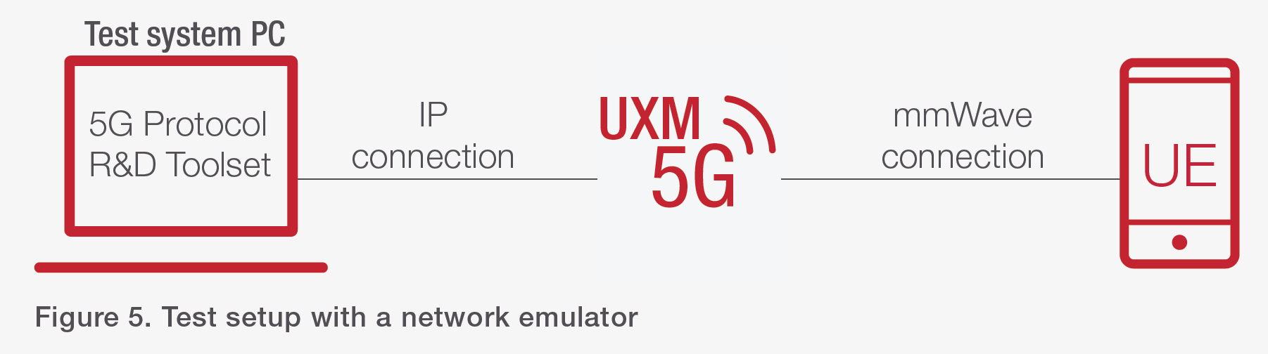
Figure 5. Test setup with a network emulator
Most component and device testing require a controlled environment. However, wireless devices need to operate in environments that have signal propagation issues, including excessive path loss, multipath fading, and delay spread. These real-world impairments impact device performance and require evaluation. Adding a channel emulator to the test setup enables the characterization of end-to-end full-stack data throughput while emulating a variety of real-world radio conditions.

Figure 6. A channel emulator, such as the Keysight PROPSIM F64, lets you evaluate under real-world conditions
Choosing the Right Tools for Evaluating Antenna Beam Patterns
MIMO, beam steering, and beamforming are critical technologies for 5G devices. Implementing multi-element antennas introduces many challenges for device designers. Having the right tools to evaluate antenna beam patterns and ensure that devices can connect to the network and deliver the expected quality of service is essential.
Keysight provides test solutions that validate beam structure and device performance on a simulated network, giving designers a seamless workflow from protocol to RF, resulting in more efficient development — even in an environment of ever-evolving 5G standards. With the addition of channel emulation, designers can validate their designs in real-world test scenarios and get high-performing products to market even quicker.
Part 4: Over-the-Air Test
Over-the-air (OTA) testing is one of the most challenging aspects of 5G device development. Designers need to address many aspects of 5G, including the 5G New Radio (NR) standard, flexible numerology, millimeter-wave (mmWave) design considerations, multiple-input / multiple-output (MIMO), and beamforming challenges. The combination of these technologies introduces substantial test challenges that require OTA testing for validation.
MIMO, beam steering, and carrier aggregation are critical to meet downlink peak data rates of up to 20 Gbps for enhanced mobile broadband use cases. Under the unique mmWave channel conditions, highly integrated modems and designs require OTA testing. In the OTA test environment, it is necessary to visualize, characterize, and validate 5G device beam patterns and performance in a variety of real-world scenarios.
However, the 3rd Generation Partnership Project (3GPP) has not yet fully defined and approved OTA tests. Understanding the underlying challenges and proposed OTA test methods is essential to successfully develop 5G NR devices.
You must address these three challenges to successfully test 5G mmWave:
- Excessive path loss and distance at mmWave frequencies
- mmWave OTA test methods not fully defined
- Measuring device performance under real-world channel conditions
New Test Methodologies Required for mmWave
Millimeter-wave frequencies are important because they offer a more contiguous spectrum and wider bandwidth radio channels. These mmWave signals are also subject to signal propagation issues that were not a problem at sub-6 GHz. These include increased path loss, delay spread, or even blockage caused by chassis or human interference. These issues make it more difficult to establish and maintain a wireless communication link. 5G radio systems use multi-antenna spatial diversity and beam-steering techniques on both base stations and mobile devices to overcome these challenges. These designs improve signal robustness by reliably directing narrow beams in specific directions.
The mmWave antenna arrays are quite small; 24 GHz full-wave spacing is just 12.5 mm. 5G smartphone manufacturers need real estate for GPS, Wi-Fi, Bluetooth, and antennas that support multiple cellular frequencies. Also, mmWave antenna arrays require physical bonding to the amplifier semiconductors for transmitting and receiving of the radio. These integrated designs are impractical to probe and cabled tests to become impossible to test mmWave parameters.

Figure 1. Device antenna locations and radiating beams from antenna arrays
OTA testing delivers critical insights during the prototyping phase. Chipsets, antennas, and integrated devices require validation in an over-the-air environment. A top-performing design requires designers to measure beam patterns both in 2D and 3D and understand beamwidth, sidelobe levels, null depths, and symmetry. Also, validating beam steering and null steering functionality are critical, confirming that the beam is pointing in the correct direction while maintaining the antenna gain under various conditions.
OTA Test Challenges and Solutions
Unlike traditional cabled tests, OTA tests introduce many new challenges, including path loss. Cabled test systems demonstrate well-behaved physical properties that need calibration to produce accurate and repeatable results. Calibrating OTA test methods is possible, but the process is more time-consuming and complex. With mmWave devices, excessive path loss makes accurate OTA measurements more difficult. And while 3GPP has not yet fully defined standards for mmWave testing, Keysight works closely with 5G chipset and device leaders to understand the OTA test challenges and deliver 5G-ready solutions. Here is a summary of the new challenges:
- excessive path loss and distance at mmWave frequencies
- mmWave OTA test methods not fully defined
- measuring device performance in real-world channel conditions
Challenge 1: Excessive path loss and distance at mmWave frequencies
OTA tests are typically carried out in either the near-field or far-field regions of the antenna array. The characteristics of the transmitted electromagnetic wave change depending on the distance from the transmitter. The signal becomes more developed as it propagates from the antenna array. As shown in Figure 2, the amplitude of the peaks, side lobes, and nulls of the radiation pattern evolve toward the far-field pattern.

Figure 2. Beam properties at different distances from the antenna array
While near-field measurements are appropriate for some applications, 5G cellular communication links require using far-field assumptions. Because of the nature of radiated waves, the far-field distance and associated path loss grow bigger with the frequency. For example, the far-field region of a 4G Long Term Evolution (LTE) 15 cm device operating at 2 GHz starts at 0.3 meters and has a path loss of 28 dB. The far-field region of a 5G NR device operating at 28 GHz has a far-field distance of 4.2 meters and a path loss of 73 dB. This distance results in an excessively large far-field test chamber, and the path loss is too great to make accurate and repeatable measurements at mmWave frequencies. The distance also grows larger as the source antenna grows bigger, compounding the size and path loss challenge.

Table 1. Estimated far-field distance and path loss for different radiating apertures
Successfully testing RF performance measurements such as transmitted power, transmit signal quality, and spurious emissions require overcoming the path loss problem. To overcome the path loss and excessive far-field distance issues, 3GPP approved an indirect far-field (IFF) test method based on a compact antenna test range (CATR), as depicted in Figure 3.

Figure 3. 5G compact antenna test range chamber
Challenge 2: mmWave OTA test methods not fully defined
A typical OTA test solution includes an anechoic chamber, different probing techniques, and test equipment to generate and analyze the radiated signals in a spatial setting. The anechoic chamber provides a nonreflective environment with shielding from outside interference to generate and measure radiated signals of known power and direction in a controlled environment.
Moving to 5G, low-frequency tests are similar to 4G. For mmWave, however, the following tests now require the use of over-the-air methods:
- RF performance – the minimum level of signal quality
- demodulation – data throughput performance
- radio resource management (RRM) – initial access, handover, and mobility
- signaling – upper layer signaling procedures
5G RF performance test methods are the most mature today. 3GPP study groups are still defining test methods for device demodulation and the more complicated RRM. 3GPP allows three RF performance test methods for user equipment (UE) devices. Each method has pros and cons, and one or more may be useful in characterizing your device based on the frequencies you need to test and the space constraints in your lab.
Direct far-field method
In the direct far-field (DFF) method, the device under test (DUT) mounts on a positioner that rotates in azimuth and elevation, enabling measurement of the DUT at any angle on the full 3D sphere. The direct far-field method can perform the most comprehensive tests measuring multiple signals but requires a larger test chamber for mmWave devices; a 4.2 m chamber for a 15 cm radiating device at 28 GHz results in excessive path loss. With the ability to measure multiple signals, this remains the preferred method for sub-6 GHz devices.

Figure 4. A direct far-field test setup
Indirect far-field method
The IFF test method is based on a CATR that uses a parabolic reflector to make the signals transmitted by the probe antenna parallel and create a far-field test environment. While this method measures a single signal, it provides a much shorter distance and with less path loss than the DFF method for measuring mmWave devices.

Figure 5. The physical arrangement of a CATR chamber
Near-field to the far-field transform method
The near-field to far-field transform (NFTF) method samples the phase and amplitude of the electrical field in the near region and uses math to predict the far-field pattern. While this is a compact, low-cost method, it is subject to transmitter interference that impacts measurement accuracy. It is also limited to single line-of-sight measurements.

Figure 6. The concept of an NFTF test method
Since specific requirements and test methods have not been fully defined, it will require a considerable amount of time and rework to implement an OTA test solution on your own. Keysight participates in the development of the 3GPP specifications and has early knowledge of requirements. Working closely with early adopters, we innovate on 5G OTA test methods, including chambers, probing, and the test equipment used to address a wide range of RF, demodulation, and functional performance test requirements in both mmWave and sub-6 GHz for 5G new radio designs.
Challenge 3: Measuring device performance in real-world conditions
To achieve the highest degree of performance and reliability, designers must move beyond testing in a stable and controlled validation environment. A channel emulator is a tool that mimics real-world conditions while providing control and repeatability for those conditions. The tool lets designers test a variety of new technologies, including wider signal bandwidths, mmWave frequencies, and beam steering with signal propagation issues like path loss, multipath fading, and delay spread. As part of a complete testbed, a channel emulator enables the designer to characterize the device as part of a live full-stack system while emulating real-world radio conditions. A full-stack setup enables designers to test a broad range of situations and quickly identify any use cases that might compromise the user experience in the finished device.

Figure 7. A base station emulator and channel emulator simulate real-world conditions
Implementing Evolving OTA Testing Methods
Delivering on the extreme data rates 5G promises will be challenging. Visualization, characterization, and validation of multi-antenna arrays that create narrow beams require OTA test methods. Far-field path loss and chamber size lead to challenges with accurate and repeatable measurements as well as physical challenges with lab space.
The 3GPP is working on specifying new OTA methods to help mitigate these challenges. Many aspects of OTA tests still need to be fully defined, but Keysight is at the forefront of 3GPP specifications and early OTA test solution development. Leverage Keysight’s expertise to accelerate 5G designs while ensuring high performance and higher-quality products. Contact Keysight to learn more about solutions for 5G OTA testing.
Source: Keysight Technologies