The latest ISACA CISA (Certified Information Systems Auditor) certification actual real practice exam question and answer (Q&A) dumps are available free, which are helpful for you to pass the ISACA CISA exam and earn ISACA CISA certification.

Table of Contents
- CISA Question 2311
- Question
- Answer
- Explanation
- CISA Question 2312
- Question
- Answer
- Explanation
- CISA Question 2313
- Question
- Answer
- Explanation
- CISA Question 2314
- Question
- Answer
- Explanation
- CISA Question 2315
- Question
- Answer
- Explanation
- CISA Question 2316
- Question
- Answer
- Explanation
- CISA Question 2317
- Question
- Answer
- Explanation
- CISA Question 2318
- Question
- Answer
- Explanation
- CISA Question 2319
- Question
- Answer
- Explanation
- CISA Question 2320
- Question
- Answer
- Explanation
CISA Question 2311
Question
Identify the WAN message switching technique being used from the description presented below:
‘Data is routed in its entirety from the source node to the destination node, one hope at a time. During message routing, every intermediate switch in the network stores the whole message. If the entire network’s resources are engaged or the network becomes blocked, this WAN switching technology stores and delays the message until ample resources become available for effective transmission of the message.’
A. Message Switching
B. Packet switching
C. Circuit switching
D. Virtual Circuits
Answer
A. Message Switching
Explanation
For your exam you should know below information about WAN message transmission technique:
Message Switching – Message switching is a network switching technique in which data is routed in its entirety from the source node to the destination node, one hope at a time. During message routing, every intermediate switch in the network stores the whole message. If the entire network’s resources are engaged or the network becomes blocked, the message-switched network stores and delays the message until ample resources become available for effective transmission of the message.

Packet Switching – Refers to protocols in which messages are divided into packets before they are sent. Each packet is then transmitted individually and can even follow different routes to its destination. Once all the packets forming a message arrive at the destination, they are recompiled into the original message.

Circuit Switching – Circuit switching is a methodology of implementing a telecommunications network in which two network nodes establish a dedicated communications channel (circuit) through the network before the nodes may communicate.
The circuit guarantees the full bandwidth of the channel and remains connected for the duration of the session. The circuit functions as if the nodes were physically connected similar to an electrical circuit.
The defining example of a circuit-switched network is the early analog telephone network. When a call is made from one telephone to another, switches within the telephone exchanges create a continuous wire circuit between the two telephones, for as long as the call lasts.
In circuit switching, the bit delay is constant during a connection, as opposed to packet switching, where packet queues may cause varying and potentially indefinitely long packet transfer delays. No circuit can be degraded by competing users because it is protected from use by other callers until the circuit is released and a new connection is set up. Even if no actual communication is taking place, the channel remains reserved and protected from competing users.

See a table below comparing Circuit Switched versus Packet Switched networks:

Virtual circuit – In telecommunications and computer networks, a virtual circuit (VC), synonymous with virtual connection and virtual channel, is a connection oriented communication service that is delivered by means of packet mode communication.
After a connection or virtual circuit is established between two nodes or application processes, a bit stream or byte stream may be delivered between the nodes; a virtual circuit protocol allows higher level protocols to avoid dealing with the division of data into segments, packets, or frames.
Virtual circuit communication resembles circuit switching, since both are connection oriented, meaning that in both cases data is delivered in correct order, and signaling overhead is required during a connection establishment phase. However, circuit switching provides constant bit rate and latency, while these may vary in a virtual circuit service due to factors such as: varying packet queue lengths in the network nodes, varying bit rate generated by the application, varying load from other users sharing the same network resources by means of statistical multiplexing, etc.
The following were incorrect answers:
The other options presented are not valid choices.
CISA Question 2312
Question
Identify the network topology from below diagram presented below:

A. Bus
B. Star
C. Ring
D. Mesh
Answer
D. Mesh
Explanation
For your exam you should know the information below related to LAN topologies:
LAN Topologies – Network topology is the physical arrangement of the various elements (links, nodes, etc.) of a computer network.
Essentially, it is the topological structure of a network, and may be depicted physically or logically. Physical topology refers to the placement of the network’s various components, including device location and cable installation, while logical topology shows how data flows within a network, regardless of its physical design.
Distances between nodes, physical interconnections, transmission rates, and/or signal types may differ between two networks, yet their topologies may be identical.
Bus – In local area networks where bus topology is used, each node is connected to a single cable. Each computer or server is connected to the single bus cable. A signal from the source travels in both directions to all machines connected on the bus cable until it finds the intended recipient. If the machine address does not match the intended address for the data, the machine ignores the data. Alternatively, if the data matches the machine address, the data is accepted. Since the bus topology consists of only one wire, it is rather inexpensive to implement when compared to other topologies. However, the low cost of implementing the technology is offset by the high cost of managing the network. Additionally, since only one cable is utilized, it can be the single point of failure. If the network cable is terminated on both ends and when without termination data transfer stop and when cable breaks, the entire network will be down.

Linear bus – The type of network topology in which all of the nodes of the network are connected to a common transmission medium which has exactly two endpoints (this is the ‘bus’, which is also commonly referred to as the backbone, or trunk) – all data that is transmitted between nodes in the network is transmitted over this common transmission medium and is able to be received by all nodes in the network simultaneously.
Distributed bus – The type of network topology in which all of the nodes of the network are connected to a common transmission medium which has more than two endpoints that are created by adding branches to the main section of the transmission medium – the physical distributed bus topology functions in exactly the same fashion as the physical linear bus topology (i.e., all nodes share a common transmission medium).
Star – In local area networks with a star topology, each network host is connected to a central point with a point-to-point connection. In Star topology every node (computer workstation or any other peripheral) is connected to central node called hub or switch.
The switch is the server and the peripherals are the clients. The network does not necessarily have to resemble a star to be classified as a star network, but all of the nodes on the network must be connected to one central device.
All traffic that traverses the network passes through the central point. The central point acts as a signal repeater.
The star topology is considered the easiest topology to design and implement. An advantage of the star topology is the simplicity of adding additional nodes. The primary disadvantage of the star topology is that the central point represents a single point of failure.

Ring – A network topology that is set up in a circular fashion in which data travels around the ring in one direction and each device on the ring acts as a repeater to keep the signal strong as it travels. Each device incorporates a receiver for the incoming signal and a transmitter to send the data on to the next device in the ring.
The network is dependent on the ability of the signal to travel around the ring. When a device sends data, it must travel through each device on the ring until it reaches its destination. Every node is a critical link. If one node goes down the whole link would be affected.

Mesh – The value of a fully meshed networks is proportional to the exponent of the number of subscribers, assuming that communicating groups of any two endpoints, up to and including all the endpoints, is approximated by Reed’s Law.
A mesh network provides for high availability and redundancy. However, the cost of such network could be very expensive if dozens of devices are in the mesh.

Fully connected mesh topology – A fully connected network is a communication network in which each of the nodes is connected to each other. In graph theory it known as a complete graph. A fully connected network doesn’t need to use switching nor broadcasting. However, its major disadvantage is that the number of connections grows quadratic ally with the number of nodes, so it is extremely impractical for large networks. A two-node network is technically a fully connected network.
Partially connected mesh topology – The type of network topology in which some of the nodes of the network are connected to more than one other node in the network with a pointto-point link – this makes it possible to take advantage of some of the redundancy that is provided by a physical fully connected mesh topology without the expense and complexity required for a connection between every node in the network.
The following answers are incorrect:
The other options presented are not valid.
CISA Question 2313
Question
Identify the network topology from below diagram presented below:
A. Bus
B. Star
C. Ring
D. Mesh
Answer
B. Star
Explanation
For your exam you should know the information below related to LAN topologies:
LAN Topologies – Network topology is the physical arrangement of the various elements (links, nodes, etc.) of a computer network.
Essentially, it is the topological structure of a network, and may be depicted physically or logically. Physical topology refers to the placement of the network’s various components, including device location and cable installation, while logical topology shows how data flows within a network, regardless of its physical design.
Distances between nodes, physical interconnections, transmission rates, and/or signal types may differ between two networks, yet their topologies may be identical.
Bus – In local area networks where bus topology is used, each node is connected to a single cable. Each computer or server is connected to the single bus cable. A signal from the source travels in both directions to all machines connected on the bus cable until it finds the intended recipient. If the machine address does not match the intended address for the data, the machine ignores the data. Alternatively, if the data matches the machine address, the data is accepted. Since the bus topology consists of only one wire, it is rather inexpensive to implement when compared to other topologies. However, the low cost of implementing the technology is offset by the high cost of managing the network. Additionally, since only one cable is utilized, it can be the single point of failure. If the network cable is terminated on both ends and when without termination data transfer stop and when cable breaks, the entire network will be down.
Linear bus – The type of network topology in which all of the nodes of the network are connected to a common transmission medium which has exactly two endpoints (this is the ‘bus’, which is also commonly referred to as the backbone, or trunk) – all data that is transmitted between nodes in the network is transmitted over this common transmission medium and is able to be received by all nodes in the network simultaneously.
Distributed bus – The type of network topology in which all of the nodes of the network are connected to a common transmission medium which has more than two endpoints that are created by adding branches to the main section of the transmission medium – the physical distributed bus topology functions in exactly the same fashion as the physical linear bus topology (i.e., all nodes share a common transmission medium).
Star – In local area networks with a star topology, each network host is connected to a central point with a point-to-point connection. In Star topology every node (computer workstation or any other peripheral) is connected to central node called hub or switch.
The switch is the server and the peripherals are the clients. The network does not necessarily have to resemble a star to be classified as a star network, but all of the nodes on the network must be connected to one central device.
All traffic that traverses the network passes through the central point. The central point acts as a signal repeater.
The star topology is considered the easiest topology to design and implement. An advantage of the star topology is the simplicity of adding additional nodes. The primary disadvantage of the star topology is that the central point represents a single point of failure.
Ring – A network topology that is set up in a circular fashion in which data travels around the ring in one direction and each device on the ring acts as a repeater to keep the signal strong as it travels. Each device incorporates a receiver for the incoming signal and a transmitter to send the data on to the next device in the ring.
The network is dependent on the ability of the signal to travel around the ring. When a device sends data, it must travel through each device on the ring until it reaches its destination. Every node is a critical link. If one node goes down the whole link would be affected.
Mesh – The value of a fully meshed networks is proportional to the exponent of the number of subscribers, assuming that communicating groups of any two endpoints, up to and including all the endpoints, is approximated by Reed’s Law.
A mesh network provides for high availability and redundancy. However, the cost of such network could be very expensive if dozens of devices are in the mesh.
Fully connected mesh topology – A fully connected network is a communication network in which each of the nodes is connected to each other. In graph theory it known as a complete graph. A fully connected network doesn’t need to use switching nor broadcasting. However, its major disadvantage is that the number of connections grows quadratic ally with the number of nodes, so it is extremely impractical for large networks. A two-node network is technically a fully connected network.
Partially connected mesh topology – The type of network topology in which some of the nodes of the network are connected to more than one other node in the network with a pointto-point link – this makes it possible to take advantage of some of the redundancy that is provided by a physical fully connected mesh topology without the expense and complexity required for a connection between every node in the network.
The following answers are incorrect:
The other options presented are not valid.
CISA Question 2314
Question
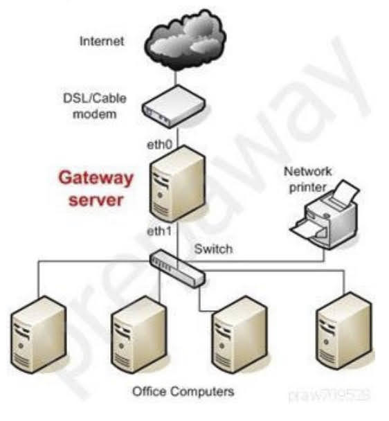
Identify the LAN topology from below diagram presented below:
A. Bus
B. Star
C. Ring
D. Mesh
Answer
A. Bus
Explanation
For your exam you should know the information below related to LAN topologies:
LAN Topologies – Network topology is the physical arrangement of the various elements (links, nodes, etc.) of a computer network.
Essentially, it is the topological structure of a network, and may be depicted physically or logically. Physical topology refers to the placement of the network’s various components, including device location and cable installation, while logical topology shows how data flows within a network, regardless of its physical design.
Distances between nodes, physical interconnections, transmission rates, and/or signal types may differ between two networks, yet their topologies may be identical.
Bus – In local area networks where bus topology is used, each node is connected to a single cable. Each computer or server is connected to the single bus cable. A signal from the source travels in both directions to all machines connected on the bus cable until it finds the intended recipient. If the machine address does not match the intended address for the data, the machine ignores the data. Alternatively, if the data matches the machine address, the data is accepted. Since the bus topology consists of only one wire, it is rather inexpensive to implement when compared to other topologies. However, the low cost of implementing the technology is offset by the high cost of managing the network. Additionally, since only one cable is utilized, it can be the single point of failure. If the network cable is terminated on both ends and when without termination data transfer stop and when cable breaks, the entire network will be down.
Linear bus – The type of network topology in which all of the nodes of the network are connected to a common transmission medium which has exactly two endpoints (this is the ‘bus’, which is also commonly referred to as the backbone, or trunk) – all data that is transmitted between nodes in the network is transmitted over this common transmission medium and is able to be received by all nodes in the network simultaneously.
Distributed bus – The type of network topology in which all of the nodes of the network are connected to a common transmission medium which has more than two endpoints that are created by adding branches to the main section of the transmission medium – the physical distributed bus topology functions in exactly the same fashion as the physical linear bus topology (i.e., all nodes share a common transmission medium).
Star – In local area networks with a star topology, each network host is connected to a central point with a point-to-point connection. In Star topology every node (computer workstation or any other peripheral) is connected to central node called hub or switch.
The switch is the server and the peripherals are the clients. The network does not necessarily have to resemble a star to be classified as a star network, but all of the nodes on the network must be connected to one central device.
All traffic that traverses the network passes through the central point. The central point acts as a signal repeater.
The star topology is considered the easiest topology to design and implement. An advantage of the star topology is the simplicity of adding additional nodes. The primary disadvantage of the star topology is that the central point represents a single point of failure.
Ring – A network topology that is set up in a circular fashion in which data travels around the ring in one direction and each device on the ring acts as a repeater to keep the signal strong as it travels. Each device incorporates a receiver for the incoming signal and a transmitter to send the data on to the next device in the ring.
The network is dependent on the ability of the signal to travel around the ring. When a device sends data, it must travel through each device on the ring until it reaches its destination. Every node is a critical link. If one node goes down the whole link would be affected.
Mesh – The value of a fully meshed networks is proportional to the exponent of the number of subscribers, assuming that communicating groups of any two endpoints, up to and including all the endpoints, is approximated by Reed’s Law.
A mesh network provides for high availability and redundancy. However, the cost of such network could be very expensive if dozens of devices are in the mesh.
Fully connected mesh topology – A fully connected network is a communication network in which each of the nodes is connected to each other. In graph theory it known as a complete graph. A fully connected network doesn’t need to use switching nor broadcasting. However, its major disadvantage is that the number of connections grows quadratic ally with the number of nodes, so it is extremely impractical for large networks. A two-node network is technically a fully connected network.
Partially connected mesh topology – The type of network topology in which some of the nodes of the network are connected to more than one other node in the network with a pointto-point link – this makes it possible to take advantage of some of the redundancy that is provided by a physical fully connected mesh topology without the expense and complexity required for a connection between every node in the network.
The following answers are incorrect:
The other options presented are not valid.
CISA Question 2315
Question
Which of the following statement INCORRECTLY describes network device such as a Router?
A. Router creates a new header for each packet
B. Router builds a routing table based on MAC address
C. Router does not forward broadcast packet
D. Router assigns a different network address per port
Answer
B. Router builds a routing table based on MAC address
Explanation
The INCORRECTLY keyword is used in the question. You need to find out a statement which is not valid about router. Router builds a routing table based on IP address and not on MAC address.
Difference between Router and Bridge:
Router –
Bridge –
Creates a new header for each packet
Does not alter header. Only reads the header
Builds routing table based on IP address
Build forwarding table based on MAC address
Assigns a different network address per port
Use the same network address for all ports
Filters traffic based on IP address
Filter traffic based on MAC address
Does not forward broadcast packet
Forward broadcast packet –
Does not forward traffic that contain destination address unknown to the router
Forward traffic if destination address is unknown to bridge
For your exam you should know below information about network devices:
Repeaters – A repeater provides the simplest type of connectivity, because it only repeats electrical signals between cable segments, which enables it to extend a network.
Repeaters work at the physical layer and are add-on devices for extending a network connection over a greater distance. The device amplifies signals because signals attenuate the farther they have to travel.
Repeaters can also work as line conditioners by actually cleaning up the signals. This works much better when amplifying digital signals than when amplifying analog signals, because digital signals are discrete units, which makes extraction of background noise from them much easier for the amplifier. If the device is amplifying analog signals, any accompanying noise often is amplified as well, which may further distort the signal.
A hub is a multi-port repeater. A hub is often referred to as a concentrator because it is the physical communication device that allows several computers and devices to communicate with each other. A hub does not understand or work with IP or MAC addresses. When one system sends a signal to go to another system connected to it, the signal is broadcast to all the ports, and thus to all the systems connected to the concentrator.

Bridges – A bridge is a LAN device used to connect LAN segments. It works at the data link layer and therefore works with MAC addresses. A repeater does not work with addresses; it just forwards all signals it receives. When a frame arrives at a bridge, the bridge determines whether or not the MAC address is on the local network segment. If the MAC address is not on the local network segment, the bridge forwards the frame to the necessary network segment.

Routers – Routers are layer 3, or network layer, devices that are used to connect similar or different networks. (For example, they can connect two Ethernet LANs or an Ethernet LAN to a Token Ring LAN.) A router is a device that has two or more interfaces and a routing table so it knows how to get packets to their destinations. It can filter traffic based on access control lists (ACLs), and it fragments packets when necessary. Because routers have more network-level knowledge, they can perform higher-level functions, such as calculating the shortest and most economical path between the sending and receiving hosts.

Switches – Switches combine the functionality of a repeater and the functionality of a bridge. A switch amplifies the electrical signal, like a repeater, and has the built-in circuitry and intelligence of a bridge. It is a multi-port connection device that provides connections for individual computers or other hubs and switches.
Gateways – Gateway is a general term for software running on a device that connects two different environments and that many times acts as a translator for them or somehow restricts their interactions.
Usually a gateway is needed when one environment speaks a different language, meaning it uses a certain protocol that the other environment does not understand. The gateway can translate Internetwork Packet Exchange (IPX) protocol packets to IP packets, accept mail from one type of mail server and format it so another type of mail server can accept and understand it, or connect and translate different data link technologies such as FDDI to Ethernet.
The following were incorrect answers:
The other options presented correctly describes about Router.
CISA Question 2316
Question
Which of the following layer of an OSI model transmits and receives the bit stream as electrical, optical or radio signals over an appropriate medium or carrier?
A. Transport Layer
B. Network Layer
C. Data Link Layer
D. Physical Layer
Answer
D. Physical Layer
Explanation
The physical layer, the lowest layer of the OSI model, is concerned with the transmission and reception of the unstructured raw bit stream over a physical medium.
It describes the electrical/optical, mechanical, and functional interfaces to the physical medium, and carries the signals for all of the higher layers.
For your exam you should know below information about OSI model:
The Open Systems Interconnection model (OSI) is a conceptual model that characterizes and standardizes the internal functions of a communication system by partitioning it into abstraction layers. The model is a product of the Open Systems Interconnection project at the International Organization for Standardization (ISO), maintained by the identification ISO/IEC 7498-1.
The model groups communication functions into seven logical layers. A layer serves the layer above it and is served by the layer below it. For example, a layer that provides error-free communications across a network provides the path needed by applications above it, while it calls the next lower layer to send and receive packets that make up the contents of that path. Two instances at one layer are connected by a horizontal.

PHYSICAL LAYER – The physical layer, the lowest layer of the OSI model, is concerned with the transmission and reception of the unstructured raw bit stream over a physical medium.
It describes the electrical/optical, mechanical, and functional interfaces to the physical medium, and carries the signals for all of the higher layers. It provides:
Data encoding: modifies the simple digital signal pattern (1s and 0s) used by the PC to better accommodate the characteristics of the physical medium, and to aid in bit and frame synchronization. It determines:
What signal state represents a binary 1
How the receiving station knows when a “bit-time” starts
How the receiving station delimits a frame
DATA LINK LAYER – The data link layer provides error-free transfer of data frames from one node to another over the physical layer, allowing layers above it to assume virtually error- free transmission over the link. To do this, the data link layer provides:
Link establishment and termination: establishes and terminates the logical link between two nodes.
Frame traffic control: tells the transmitting node to “back-off” when no frame buffers are available.
Frame sequencing: transmits/receives frames sequentially.
Frame acknowledgment: provides/expects frame acknowledgments. Detects and recovers from errors that occur in the physical layer by retransmitting non- acknowledged frames and handling duplicate frame receipt.
Frame delimiting: creates and recognizes frame boundaries.
Frame error checking: checks received frames for integrity.
Media access management: determines when the node “has the right” to use the physical medium.
NETWORK LAYER – The network layer controls the operation of the subnet, deciding which physical path the data should take based on network conditions, priority of service, and other factors. It provides:
Routing: routes frames among networks.
Subnet traffic control: routers (network layer intermediate systems) can instruct a sending station to “throttle back” its frame transmission when the router’s buffer fills up.
Frame fragmentation: if it determines that a downstream router’s maximum transmission unit (MTU) size is less than the frame size, a router can fragment a frame for transmission and re-assembly at the destination station.
Logical-physical address mapping: translates logical addresses, or names, into physical addresses.
Subnet usage accounting: has accounting functions to keep track of frames forwarded by subnet intermediate systems, to produce billing information.
Communications Subnet – The network layer software must build headers so that the network layer software residing in the subnet intermediate systems can recognize them and use them to route data to the destination address.
This layer relieves the upper layers of the need to know anything about the data transmission and intermediate switching technologies used to connect systems. It establishes, maintains and terminates connections across the intervening communications facility (one or several intermediate systems in the communication subnet).
In the network layer and the layers below, peer protocols exist between a node and its immediate neighbor, but the neighbor may be a node through which data is routed, not the destination station. The source and destination stations may be separated by many intermediate systems.
TRANSPORT LAYER – The transport layer ensures that messages are delivered error-free, in sequence, and with no losses or duplications. It relieves the higher layer protocols from any concern with the transfer of data between them and their peers.
The size and complexity of a transport protocol depends on the type of service it can get from the network layer. For a reliable network layer with virtual circuit capability, a minimal transport layer is required. If the network layer is unreliable and/or only supports datagram’s, the transport protocol should include extensive error detection and recovery.
The transport layer provides:
Message segmentation: accepts a message from the (session) layer above it, splits the message into smaller units (if not already small enough), and passes the smaller units down to the network layer. The transport layer at the destination station reassembles the message.
Message acknowledgment: provides reliable end-to-end message delivery with acknowledgments.
Message traffic control: tells the transmitting station to “back-off” when no message buffers are available.
Session multiplexing: multiplexes several message streams, or sessions onto one logical link and keeps track of which messages belong to which sessions (see session layer).
Typically, the transport layer can accept relatively large messages, but there are strict message size limits imposed by the network (or lower) layer. Consequently, the transport layer must break up the messages into smaller units, or frames, pretending a header to each frame.
The transport layer header information must then include control information, such as message start and message end flags, to enable the transport layer on the other end to recognize message boundaries. In addition, if the lower layers do not maintain sequence, the transport header must contain sequence information to enable the transport layer on the receiving end to get the pieces back together in the right order before handing the received message up to the layer above.
End-to-end layers – Unlike the lower “subnet” layers whose protocol is between immediately adjacent nodes, the transport layer and the layers above are true “source to destination” or end-to-end layers, and are not concerned with the details of the underlying communications facility. Transport layer software (and software above it) on the source station carries on a conversation with similar software on the destination station by using message headers and control messages.
SESSION LAYER – The session layer allows session establishment between processes running on different stations. It provides:
Session establishment, maintenance and termination: allows two application processes on different machines to establish, use and terminate a connection, called a session.
Session support: performs the functions that allow these processes to communicate over the network, performing security, name recognition, logging, and so on.
PRESENTATION LAYER –
The presentation layer formats the data to be presented to the application layer. It can be viewed as the translator for the network. This layer may translate data from a format used by the application layer into a common format at the sending station, then translate the common format to a format known to the application layer at the receiving station.
The presentation layer provides:
Character code translation: for example, ASCII to EBCDIC.
Data conversion: bit order, CR-CR/LF, integer-floating point, and so on.
Data compression: reduces the number of bits that need to be transmitted on the network.
Data encryption: encrypt data for security purposes. For example, password encryption.
APPLICATION LAYER – The application layer serves as the window for users and application processes to access network services. This layer contains a variety of commonly needed functions:
Resource sharing and device redirection
Remote file access –
Remote printer access –
Inter-process communication –
Network management –
Directory services –
Electronic messaging (such as mail)
Network virtual terminals –
The following were incorrect answers:
Transport layer – The transport layer ensures that messages are delivered error-free, in sequence, and with no losses or duplications. It relieves the higher layer protocols from any concern with the transfer of data between them and their peers.
Network layer – The network layer controls the operation of the subnet, deciding which physical path the data should take based on network conditions, priority of service, and other factors.
Data link layer – The data link layer provides error-free transfer of data frames from one node to another over the physical layer, allowing layers above it to assume virtually error-free transmission over the link.
CISA Question 2317
Question
Which of the following layer of an OSI model encapsulates packets into frames?
A. Transport Layer
B. Network Layer
C. Data Link Layer
D. Physical Layer .
Answer
C. Data Link Layer
Explanation
The data link layer provides error-free transfer of data frames from one node to another over the physical layer, allowing layers above it to assume virtually error- free transmission over the link.
For your exam you should know below information about OSI model:
The Open Systems Interconnection model (OSI) is a conceptual model that characterizes and standardizes the internal functions of a communication system by partitioning it into abstraction layers. The model is a product of the Open Systems Interconnection project at the International Organization for Standardization (ISO), maintained by the identification ISO/IEC 7498-1.
The model groups communication functions into seven logical layers. A layer serves the layer above it and is served by the layer below it. For example, a layer that provides error-free communications across a network provides the path needed by applications above it, while it calls the next lower layer to send and receive packets that make up the contents of that path. Two instances at one layer are connected by a horizontal.
PHYSICAL LAYER – The physical layer, the lowest layer of the OSI model, is concerned with the transmission and reception of the unstructured raw bit stream over a physical medium.
It describes the electrical/optical, mechanical, and functional interfaces to the physical medium, and carries the signals for all of the higher layers. It provides:
Data encoding: modifies the simple digital signal pattern (1s and 0s) used by the PC to better accommodate the characteristics of the physical medium, and to aid in bit and frame synchronization. It determines:
What signal state represents a binary 1
How the receiving station knows when a “bit-time” starts
How the receiving station delimits a frame
DATA LINK LAYER – The data link layer provides error-free transfer of data frames from one node to another over the physical layer, allowing layers above it to assume virtually error- free transmission over the link. To do this, the data link layer provides:
Link establishment and termination: establishes and terminates the logical link between two nodes.
Frame traffic control: tells the transmitting node to “back-off” when no frame buffers are available.
Frame sequencing: transmits/receives frames sequentially.
Frame acknowledgment: provides/expects frame acknowledgments. Detects and recovers from errors that occur in the physical layer by retransmitting non- acknowledged frames and handling duplicate frame receipt.
Frame delimiting: creates and recognizes frame boundaries.
Frame error checking: checks received frames for integrity.
Media access management: determines when the node “has the right” to use the physical medium.
NETWORK LAYER – The network layer controls the operation of the subnet, deciding which physical path the data should take based on network conditions, priority of service, and other factors. It provides:
Routing: routes frames among networks.
Subnet traffic control: routers (network layer intermediate systems) can instruct a sending station to “throttle back” its frame transmission when the router’s buffer fills up.
Frame fragmentation: if it determines that a downstream router’s maximum transmission unit (MTU) size is less than the frame size, a router can fragment a frame for transmission and re-assembly at the destination station.
Logical-physical address mapping: translates logical addresses, or names, into physical addresses.
Subnet usage accounting: has accounting functions to keep track of frames forwarded by subnet intermediate systems, to produce billing information.
Communications Subnet – The network layer software must build headers so that the network layer software residing in the subnet intermediate systems can recognize them and use them to route data to the destination address.
This layer relieves the upper layers of the need to know anything about the data transmission and intermediate switching technologies used to connect systems. It establishes, maintains and terminates connections across the intervening communications facility (one or several intermediate systems in the communication subnet).
In the network layer and the layers below, peer protocols exist between a node and its immediate neighbor, but the neighbor may be a node through which data is routed, not the destination station. The source and destination stations may be separated by many intermediate systems.
TRANSPORT LAYER – The transport layer ensures that messages are delivered error-free, in sequence, and with no losses or duplications. It relieves the higher layer protocols from any concern with the transfer of data between them and their peers.
The size and complexity of a transport protocol depends on the type of service it can get from the network layer. For a reliable network layer with virtual circuit capability, a minimal transport layer is required. If the network layer is unreliable and/or only supports datagram’s, the transport protocol should include extensive error detection and recovery.
The transport layer provides:
Message segmentation: accepts a message from the (session) layer above it, splits the message into smaller units (if not already small enough), and passes the smaller units down to the network layer. The transport layer at the destination station reassembles the message.
Message acknowledgment: provides reliable end-to-end message delivery with acknowledgments.
Message traffic control: tells the transmitting station to “back-off” when no message buffers are available.
Session multiplexing: multiplexes several message streams, or sessions onto one logical link and keeps track of which messages belong to which sessions (see session layer).
Typically, the transport layer can accept relatively large messages, but there are strict message size limits imposed by the network (or lower) layer. Consequently, the transport layer must break up the messages into smaller units, or frames, pretending a header to each frame.
The transport layer header information must then include control information, such as message start and message end flags, to enable the transport layer on the other end to recognize message boundaries. In addition, if the lower layers do not maintain sequence, the transport header must contain sequence information to enable the transport layer on the receiving end to get the pieces back together in the right order before handing the received message up to the layer above.
End-to-end layers – Unlike the lower “subnet” layers whose protocol is between immediately adjacent nodes, the transport layer and the layers above are true “source to destination” or end-to-end layers, and are not concerned with the details of the underlying communications facility. Transport layer software (and software above it) on the source station carries on a conversation with similar software on the destination station by using message headers and control messages.
SESSION LAYER – The session layer allows session establishment between processes running on different stations. It provides:
Session establishment, maintenance and termination: allows two application processes on different machines to establish, use and terminate a connection, called a session.
Session support: performs the functions that allow these processes to communicate over the network, performing security, name recognition, logging, and so on.
PRESENTATION LAYER –
The presentation layer formats the data to be presented to the application layer. It can be viewed as the translator for the network. This layer may translate data from a format used by the application layer into a common format at the sending station, then translate the common format to a format known to the application layer at the receiving station.
The presentation layer provides:
Character code translation: for example, ASCII to EBCDIC.
Data conversion: bit order, CR-CR/LF, integer-floating point, and so on.
Data compression: reduces the number of bits that need to be transmitted on the network.
Data encryption: encrypt data for security purposes. For example, password encryption.
APPLICATION LAYER – The application layer serves as the window for users and application processes to access network services. This layer contains a variety of commonly needed functions:
Resource sharing and device redirection
Remote file access –
Remote printer access –
Inter-process communication –
Network management –
Directory services –
Electronic messaging (such as mail)
Network virtual terminals –
The following were incorrect answers:
Transport layer – The transport layer ensures that messages are delivered error-free, in sequence, and with no losses or duplications. It relieves the higher layer protocols from any concern with the transfer of data between them and their peers.
Network layer – The network layer controls the operation of the subnet, deciding which physical path the data should take based on network conditions, priority of service, and other factors.
Physical Layer – The physical layer, the lowest layer of the OSI model, is concerned with the transmission and reception of the unstructured raw bit stream over a physical medium. It describes the electrical/optical, mechanical, and functional interfaces to the physical medium, and carries the signals for all of the higher layers.
CISA Question 2318
Question
Which of the following layer of an OSI model responsible for routing and forwarding of a network packets?
A. Transport Layer
B. Network Layer
C. Data Link Layer
D. Physical Layer
Answer
B. Network Layer
Explanation
The network layer controls the operation of the subnet, deciding which physical path the data should take based on network conditions, priority of service, and other factors.
For your exam you should know below information about OSI model:
The Open Systems Interconnection model (OSI) is a conceptual model that characterizes and standardizes the internal functions of a communication system by partitioning it into abstraction layers. The model is a product of the Open Systems Interconnection project at the International Organization for Standardization (ISO), maintained by the identification ISO/IEC 7498-1.
The model groups communication functions into seven logical layers. A layer serves the layer above it and is served by the layer below it. For example, a layer that provides error-free communications across a network provides the path needed by applications above it, while it calls the next lower layer to send and receive packets that make up the contents of that path. Two instances at one layer are connected by a horizontal.
PHYSICAL LAYER – The physical layer, the lowest layer of the OSI model, is concerned with the transmission and reception of the unstructured raw bit stream over a physical medium.
It describes the electrical/optical, mechanical, and functional interfaces to the physical medium, and carries the signals for all of the higher layers. It provides:
Data encoding: modifies the simple digital signal pattern (1s and 0s) used by the PC to better accommodate the characteristics of the physical medium, and to aid in bit and frame synchronization. It determines:
What signal state represents a binary 1
How the receiving station knows when a “bit-time” starts
How the receiving station delimits a frame
DATA LINK LAYER – The data link layer provides error-free transfer of data frames from one node to another over the physical layer, allowing layers above it to assume virtually error- free transmission over the link. To do this, the data link layer provides:
Link establishment and termination: establishes and terminates the logical link between two nodes.
Frame traffic control: tells the transmitting node to “back-off” when no frame buffers are available.
Frame sequencing: transmits/receives frames sequentially.
Frame acknowledgment: provides/expects frame acknowledgments. Detects and recovers from errors that occur in the physical layer by retransmitting non- acknowledged frames and handling duplicate frame receipt.
Frame delimiting: creates and recognizes frame boundaries.
Frame error checking: checks received frames for integrity.
Media access management: determines when the node “has the right” to use the physical medium.
NETWORK LAYER – The network layer controls the operation of the subnet, deciding which physical path the data should take based on network conditions, priority of service, and other factors. It provides:
Routing: routes frames among networks.
Subnet traffic control: routers (network layer intermediate systems) can instruct a sending station to “throttle back” its frame transmission when the router’s buffer fills up.
Frame fragmentation: if it determines that a downstream router’s maximum transmission unit (MTU) size is less than the frame size, a router can fragment a frame for transmission and re-assembly at the destination station.
Logical-physical address mapping: translates logical addresses, or names, into physical addresses.
Subnet usage accounting: has accounting functions to keep track of frames forwarded by subnet intermediate systems, to produce billing information.
Communications Subnet – The network layer software must build headers so that the network layer software residing in the subnet intermediate systems can recognize them and use them to route data to the destination address.
This layer relieves the upper layers of the need to know anything about the data transmission and intermediate switching technologies used to connect systems. It establishes, maintains and terminates connections across the intervening communications facility (one or several intermediate systems in the communication subnet).
In the network layer and the layers below, peer protocols exist between a node and its immediate neighbor, but the neighbor may be a node through which data is routed, not the destination station. The source and destination stations may be separated by many intermediate systems.
TRANSPORT LAYER – The transport layer ensures that messages are delivered error-free, in sequence, and with no losses or duplications. It relieves the higher layer protocols from any concern with the transfer of data between them and their peers.
The size and complexity of a transport protocol depends on the type of service it can get from the network layer. For a reliable network layer with virtual circuit capability, a minimal transport layer is required. If the network layer is unreliable and/or only supports datagram’s, the transport protocol should include extensive error detection and recovery.
The transport layer provides:
Message segmentation: accepts a message from the (session) layer above it, splits the message into smaller units (if not already small enough), and passes the smaller units down to the network layer. The transport layer at the destination station reassembles the message.
Message acknowledgment: provides reliable end-to-end message delivery with acknowledgments.
Message traffic control: tells the transmitting station to “back-off” when no message buffers are available.
Session multiplexing: multiplexes several message streams, or sessions onto one logical link and keeps track of which messages belong to which sessions (see session layer).
Typically, the transport layer can accept relatively large messages, but there are strict message size limits imposed by the network (or lower) layer. Consequently, the transport layer must break up the messages into smaller units, or frames, pretending a header to each frame.
The transport layer header information must then include control information, such as message start and message end flags, to enable the transport layer on the other end to recognize message boundaries. In addition, if the lower layers do not maintain sequence, the transport header must contain sequence information to enable the transport layer on the receiving end to get the pieces back together in the right order before handing the received message up to the layer above.
End-to-end layers – Unlike the lower “subnet” layers whose protocol is between immediately adjacent nodes, the transport layer and the layers above are true “source to destination” or end-to-end layers, and are not concerned with the details of the underlying communications facility. Transport layer software (and software above it) on the source station carries on a conversation with similar software on the destination station by using message headers and control messages.
SESSION LAYER – The session layer allows session establishment between processes running on different stations. It provides:
Session establishment, maintenance and termination: allows two application processes on different machines to establish, use and terminate a connection, called a session.
Session support: performs the functions that allow these processes to communicate over the network, performing security, name recognition, logging, and so on.
PRESENTATION LAYER –
The presentation layer formats the data to be presented to the application layer. It can be viewed as the translator for the network. This layer may translate data from a format used by the application layer into a common format at the sending station, then translate the common format to a format known to the application layer at the receiving station.
The presentation layer provides:
Character code translation: for example, ASCII to EBCDIC.
Data conversion: bit order, CR-CR/LF, integer-floating point, and so on.
Data compression: reduces the number of bits that need to be transmitted on the network.
Data encryption: encrypt data for security purposes. For example, password encryption.
APPLICATION LAYER – The application layer serves as the window for users and application processes to access network services. This layer contains a variety of commonly needed functions:
Resource sharing and device redirection
Remote file access –
Remote printer access –
Inter-process communication –
Network management –
Directory services –
Electronic messaging (such as mail)
Network virtual terminals –
The following were incorrect answers:
Transport layer – The transport layer ensures that messages are delivered error-free, in sequence, and with no losses or duplications. It relieves the higher layer protocols from any concern with the transfer of data between them and their peers.
Data link layer – The data link layer provides error-free transfer of data frames from one node to another over the physical layer, allowing layers above it to assume virtually error-free transmission over the link.
Physical Layer – The physical layer, the lowest layer of the OSI model, is concerned with the transmission and reception of the unstructured raw bit stream over a physical medium. It describes the electrical/optical, mechanical, and functional interfaces to the physical medium, and carries the signals for all of the higher layers.
CISA Question 2319
Question
Which of the following layer of an OSI model ensures that messages are delivered error-free, in sequence, and with no losses or duplications?
A. Application layer
B. Presentation layer
C. Session layer
D. Transport layer
Answer
D. Transport layer
Explanation
The transport layer ensures that messages are delivered error-free, in sequence, and with no losses or duplications. It relieves the higher layer protocols from any concern with the transfer of data between them and their peers.
The size and complexity of a transport protocol depends on the type of service it can get from the network layer. For a reliable network layer with virtual circuit capability, a minimal transport layer is required. If the network layer is unreliable and/or only supports datagram’s, the transport protocol should include extensive error detection and recovery.
The transport layer provides:
Message segmentation: accepts a message from the (session) layer above it, splits the message into smaller units (if not already small enough), and passes the smaller units down to the network layer. The transport layer at the destination station reassembles the message.
Message acknowledgment: provides reliable end-to-end message delivery with acknowledgments.
Message traffic control: tells the transmitting station to “back-off” when no message buffers are available.
Session multiplexing: multiplexes several message streams, or sessions onto one logical link and keeps track of which messages belong to which sessions (see session layer).
For your exam you should know below information about OSI model:
The Open Systems Interconnection model (OSI) is a conceptual model that characterizes and standardizes the internal functions of a communication system by partitioning it into abstraction layers. The model is a product of the Open Systems Interconnection project at the International Organization for Standardization (ISO), maintained by the identification ISO/IEC 7498-1.
The model groups communication functions into seven logical layers. A layer serves the layer above it and is served by the layer below it. For example, a layer that provides error-free communications across a network provides the path needed by applications above it, while it calls the next lower layer to send and receive packets that make up the contents of that path. Two instances at one layer are connected by a horizontal.
PHYSICAL LAYER – The physical layer, the lowest layer of the OSI model, is concerned with the transmission and reception of the unstructured raw bit stream over a physical medium.
It describes the electrical/optical, mechanical, and functional interfaces to the physical medium, and carries the signals for all of the higher layers. It provides:
Data encoding: modifies the simple digital signal pattern (1s and 0s) used by the PC to better accommodate the characteristics of the physical medium, and to aid in bit and frame synchronization. It determines:
What signal state represents a binary 1
How the receiving station knows when a “bit-time” starts
How the receiving station delimits a frame
DATA LINK LAYER – The data link layer provides error-free transfer of data frames from one node to another over the physical layer, allowing layers above it to assume virtually error- free transmission over the link. To do this, the data link layer provides:
Link establishment and termination: establishes and terminates the logical link between two nodes.
Frame traffic control: tells the transmitting node to “back-off” when no frame buffers are available.
Frame sequencing: transmits/receives frames sequentially.
Frame acknowledgment: provides/expects frame acknowledgments. Detects and recovers from errors that occur in the physical layer by retransmitting non- acknowledged frames and handling duplicate frame receipt.
Frame delimiting: creates and recognizes frame boundaries.
Frame error checking: checks received frames for integrity.
Media access management: determines when the node “has the right” to use the physical medium.
NETWORK LAYER – The network layer controls the operation of the subnet, deciding which physical path the data should take based on network conditions, priority of service, and other factors. It provides:
Routing: routes frames among networks.
Subnet traffic control: routers (network layer intermediate systems) can instruct a sending station to “throttle back” its frame transmission when the router’s buffer fills up.
Frame fragmentation: if it determines that a downstream router’s maximum transmission unit (MTU) size is less than the frame size, a router can fragment a frame for transmission and re-assembly at the destination station.
Logical-physical address mapping: translates logical addresses, or names, into physical addresses.
Subnet usage accounting: has accounting functions to keep track of frames forwarded by subnet intermediate systems, to produce billing information.
Communications Subnet – The network layer software must build headers so that the network layer software residing in the subnet intermediate systems can recognize them and use them to route data to the destination address.
This layer relieves the upper layers of the need to know anything about the data transmission and intermediate switching technologies used to connect systems. It establishes, maintains and terminates connections across the intervening communications facility (one or several intermediate systems in the communication subnet).
In the network layer and the layers below, peer protocols exist between a node and its immediate neighbor, but the neighbor may be a node through which data is routed, not the destination station. The source and destination stations may be separated by many intermediate systems.
TRANSPORT LAYER – The transport layer ensures that messages are delivered error-free, in sequence, and with no losses or duplications. It relieves the higher layer protocols from any concern with the transfer of data between them and their peers.
The size and complexity of a transport protocol depends on the type of service it can get from the network layer. For a reliable network layer with virtual circuit capability, a minimal transport layer is required. If the network layer is unreliable and/or only supports datagram’s, the transport protocol should include extensive error detection and recovery.
The transport layer provides:
Message segmentation: accepts a message from the (session) layer above it, splits the message into smaller units (if not already small enough), and passes the smaller units down to the network layer. The transport layer at the destination station reassembles the message.
Message acknowledgment: provides reliable end-to-end message delivery with acknowledgments.
Message traffic control: tells the transmitting station to “back-off” when no message buffers are available.
Session multiplexing: multiplexes several message streams, or sessions onto one logical link and keeps track of which messages belong to which sessions (see session layer).
Typically, the transport layer can accept relatively large messages, but there are strict message size limits imposed by the network (or lower) layer. Consequently, the transport layer must break up the messages into smaller units, or frames, pretending a header to each frame.
The transport layer header information must then include control information, such as message start and message end flags, to enable the transport layer on the other end to recognize message boundaries. In addition, if the lower layers do not maintain sequence, the transport header must contain sequence information to enable the transport layer on the receiving end to get the pieces back together in the right order before handing the received message up to the layer above.
End-to-end layers – Unlike the lower “subnet” layers whose protocol is between immediately adjacent nodes, the transport layer and the layers above are true “source to destination” or end-to-end layers, and are not concerned with the details of the underlying communications facility. Transport layer software (and software above it) on the source station carries on a conversation with similar software on the destination station by using message headers and control messages.
SESSION LAYER – The session layer allows session establishment between processes running on different stations. It provides:
Session establishment, maintenance and termination: allows two application processes on different machines to establish, use and terminate a connection, called a session.
Session support: performs the functions that allow these processes to communicate over the network, performing security, name recognition, logging, and so on.
PRESENTATION LAYER –
The presentation layer formats the data to be presented to the application layer. It can be viewed as the translator for the network. This layer may translate data from a format used by the application layer into a common format at the sending station, then translate the common format to a format known to the application layer at the receiving station.
The presentation layer provides:
Character code translation: for example, ASCII to EBCDIC.
Data conversion: bit order, CR-CR/LF, integer-floating point, and so on.
Data compression: reduces the number of bits that need to be transmitted on the network.
Data encryption: encrypt data for security purposes. For example, password encryption.
APPLICATION LAYER – The application layer serves as the window for users and application processes to access network services. This layer contains a variety of commonly needed functions:
Resource sharing and device redirection
Remote file access –
Remote printer access –
Inter-process communication –
Network management –
Directory services –
Electronic messaging (such as mail)
Network virtual terminals –
The following were incorrect answers:
Application Layer – The application layer serves as the window for users and application processes to access network services.
Presentation layer – The presentation layer formats the data to be presented to the application layer. It can be viewed as the translator for the network. This layer may translate data from a format used by the application layer into a common format at the sending station, then translate the common format to a format known to the application layer at the receiving station.
Session layer – The session layer allows session establishment between processes running on different stations.
CISA Question 2320
Question
Which of the following layer of an OSI model controls dialog between computers?
A. Application layer
B. Presentation layer
C. Session layer
D. Transport layer
Answer
C. Session layer
Explanation
The session layer allows session establishment between processes running on different stations. It provides:
Session establishment, maintenance and termination: allows two application processes on different machines to establish, use and terminate a connection, called a session.
Session support: performs the functions that allow these processes to communicate over the network, performing security, name recognition, logging, and so on.
For your exam you should know below information about OSI model:
The Open Systems Interconnection model (OSI) is a conceptual model that characterizes and standardizes the internal functions of a communication system by partitioning it into abstraction layers. The model is a product of the Open Systems Interconnection project at the International Organization for Standardization (ISO), maintained by the identification ISO/IEC 7498-1.
The model groups communication functions into seven logical layers. A layer serves the layer above it and is served by the layer below it. For example, a layer that provides error-free communications across a network provides the path needed by applications above it, while it calls the next lower layer to send and receive packets that make up the contents of that path. Two instances at one layer are connected by a horizontal.
PHYSICAL LAYER – The physical layer, the lowest layer of the OSI model, is concerned with the transmission and reception of the unstructured raw bit stream over a physical medium.
It describes the electrical/optical, mechanical, and functional interfaces to the physical medium, and carries the signals for all of the higher layers. It provides:
Data encoding: modifies the simple digital signal pattern (1s and 0s) used by the PC to better accommodate the characteristics of the physical medium, and to aid in bit and frame synchronization. It determines:
What signal state represents a binary 1
How the receiving station knows when a “bit-time” starts
How the receiving station delimits a frame
DATA LINK LAYER – The data link layer provides error-free transfer of data frames from one node to another over the physical layer, allowing layers above it to assume virtually error- free transmission over the link. To do this, the data link layer provides:
Link establishment and termination: establishes and terminates the logical link between two nodes.
Frame traffic control: tells the transmitting node to “back-off” when no frame buffers are available.
Frame sequencing: transmits/receives frames sequentially.
Frame acknowledgment: provides/expects frame acknowledgments. Detects and recovers from errors that occur in the physical layer by retransmitting non- acknowledged frames and handling duplicate frame receipt.
Frame delimiting: creates and recognizes frame boundaries.
Frame error checking: checks received frames for integrity.
Media access management: determines when the node “has the right” to use the physical medium.
NETWORK LAYER – The network layer controls the operation of the subnet, deciding which physical path the data should take based on network conditions, priority of service, and other factors. It provides:
Routing: routes frames among networks.
Subnet traffic control: routers (network layer intermediate systems) can instruct a sending station to “throttle back” its frame transmission when the router’s buffer fills up.
Frame fragmentation: if it determines that a downstream router’s maximum transmission unit (MTU) size is less than the frame size, a router can fragment a frame for transmission and re-assembly at the destination station.
Logical-physical address mapping: translates logical addresses, or names, into physical addresses.
Subnet usage accounting: has accounting functions to keep track of frames forwarded by subnet intermediate systems, to produce billing information.
Communications Subnet – The network layer software must build headers so that the network layer software residing in the subnet intermediate systems can recognize them and use them to route data to the destination address.
This layer relieves the upper layers of the need to know anything about the data transmission and intermediate switching technologies used to connect systems. It establishes, maintains and terminates connections across the intervening communications facility (one or several intermediate systems in the communication subnet).
In the network layer and the layers below, peer protocols exist between a node and its immediate neighbor, but the neighbor may be a node through which data is routed, not the destination station. The source and destination stations may be separated by many intermediate systems.
TRANSPORT LAYER – The transport layer ensures that messages are delivered error-free, in sequence, and with no losses or duplications. It relieves the higher layer protocols from any concern with the transfer of data between them and their peers.
The size and complexity of a transport protocol depends on the type of service it can get from the network layer. For a reliable network layer with virtual circuit capability, a minimal transport layer is required. If the network layer is unreliable and/or only supports datagram’s, the transport protocol should include extensive error detection and recovery.
The transport layer provides:
Message segmentation: accepts a message from the (session) layer above it, splits the message into smaller units (if not already small enough), and passes the smaller units down to the network layer. The transport layer at the destination station reassembles the message.
Message acknowledgment: provides reliable end-to-end message delivery with acknowledgments.
Message traffic control: tells the transmitting station to “back-off” when no message buffers are available.
Session multiplexing: multiplexes several message streams, or sessions onto one logical link and keeps track of which messages belong to which sessions (see session layer).
Typically, the transport layer can accept relatively large messages, but there are strict message size limits imposed by the network (or lower) layer. Consequently, the transport layer must break up the messages into smaller units, or frames, pretending a header to each frame.
The transport layer header information must then include control information, such as message start and message end flags, to enable the transport layer on the other end to recognize message boundaries. In addition, if the lower layers do not maintain sequence, the transport header must contain sequence information to enable the transport layer on the receiving end to get the pieces back together in the right order before handing the received message up to the layer above.
End-to-end layers – Unlike the lower “subnet” layers whose protocol is between immediately adjacent nodes, the transport layer and the layers above are true “source to destination” or end-to-end layers, and are not concerned with the details of the underlying communications facility. Transport layer software (and software above it) on the source station carries on a conversation with similar software on the destination station by using message headers and control messages.
SESSION LAYER – The session layer allows session establishment between processes running on different stations. It provides:
Session establishment, maintenance and termination: allows two application processes on different machines to establish, use and terminate a connection, called a session.
Session support: performs the functions that allow these processes to communicate over the network, performing security, name recognition, logging, and so on.
PRESENTATION LAYER –
The presentation layer formats the data to be presented to the application layer. It can be viewed as the translator for the network. This layer may translate data from a format used by the application layer into a common format at the sending station, then translate the common format to a format known to the application layer at the receiving station.
The presentation layer provides:
Character code translation: for example, ASCII to EBCDIC.
Data conversion: bit order, CR-CR/LF, integer-floating point, and so on.
Data compression: reduces the number of bits that need to be transmitted on the network.
Data encryption: encrypt data for security purposes. For example, password encryption.
APPLICATION LAYER – The application layer serves as the window for users and application processes to access network services. This layer contains a variety of commonly needed functions:
Resource sharing and device redirection
Remote file access –
Remote printer access –
Inter-process communication –
Network management –
Directory services –
Electronic messaging (such as mail)
Network virtual terminals –
The following were incorrect answers:
Application Layer – The application layer serves as the window for users and application processes to access network services.
Presentation layer – The presentation layer formats the data to be presented to the application layer. It can be viewed as the translator for the network. This layer may translate data from a format used by the application layer into a common format at the sending station, then translate the common format to a format known to the application layer at the receiving station.
Transport layer – The transport layer ensures that messages are delivered error-free, in sequence, and with no losses or duplications. It relieves the higher layer protocols from any concern with the transfer of data between them and their peers.